Replacing the Charge Rack PCB
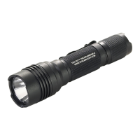
A. Unscrew the Phillips head screw located above the single base plate mounting post.
Mounting Screw
B. Carefully lift the PCB assembly straight up and out of the charger housing.
C. Obtain the proper replacement assembly.
1. Standard PCB P/N 440115.
Standard Rack.
2. Vehicle Mount PCB P/N 440114.
D. Reassemble the charge rack.
1. Carefully align the charge pins and LED's with their respective
openings.
2. Seat the PC Board in the charger housing.
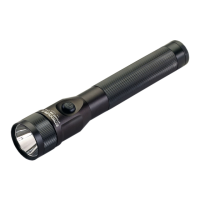
Rib must be inside
charge rack.
3. Secure the PC Board with the Phillips screw.
4. Hold the charger rack housing with the charger latch pointing
downward.
5. Make sure that the charger latch is properly seated.
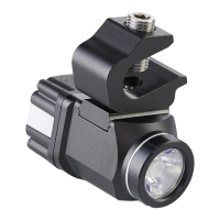
6. Place the power input connector in the opening in the charger rack.
a. The keyed slot should point toward the charger base.
b. The strain relief rib must be inside the charge rack opening.
7. Align the bottom cover and snap it into place.
Direct Wire Rack.
- 28 -