2.0 YOUR RECEIVER
2.1 DEFAULT PIN: 0000
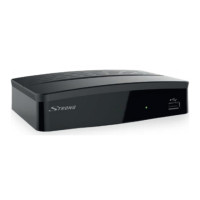
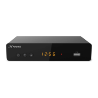
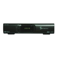
2.2 Front Panel
Fig. 1
1. IR Sensor Receives commands from the remote control
2. LED Display Shows channel number and time in standby
3. Mode Indicator LED
RED indicates that the receiver is in STANDBY mode.
4. Standby/ON button
Switches the receiver ON or into Standby
5. USB To connect your USB storage device.
2.3 Rear Panel
Fig. 2
1. ANT IN To connect to your antenna for reception of broadcast signals.
2. ETHERNET To connect to your Ethernet cable (RJ-45) for RSS feeds and
weather forecasts
3. S/PDIF Coaxial To connect your receiver to a digital home cinema set, AV
receiver or digital audio amplifier
4. HDMI To connect your receiver with your TV-set using an HDMI cable.
5. TV SCART To connect your receiver with your TV-set using a SCART cable.
6. Power cord To connect to the main power (100 - 240 V AC ~ 50/60 Hz)
7. Power switch To switch the receiver on or off.
2.4 Remote control
Fig. 3
1. q Switches the receiver On/Standby.
2. ! Mutes all audio outputs of the receiver
3. 0~9 Enter channel number in TV mode or value input in menu
4. TV/R Toggles between TV or RADIO mode.
5. No function
6. FAV Opens the favourite group selection.
7. 9 One step back in menu or back to previous channel.
8. AUDIO Opens the audio* language selection
9.
Opens the current channel information; 2x opens the current
event information and 3x the next event information.*
10. EPG Opens the EPG* (Electronic Programme Guide) in TV mode.
11. pq Change channel to next/previous.
Menu: Moves the cursor up/down.
12. tu Decreases/increases the volume level.
Menu: Change settings for specific menus.
5