5
INSTALLATION
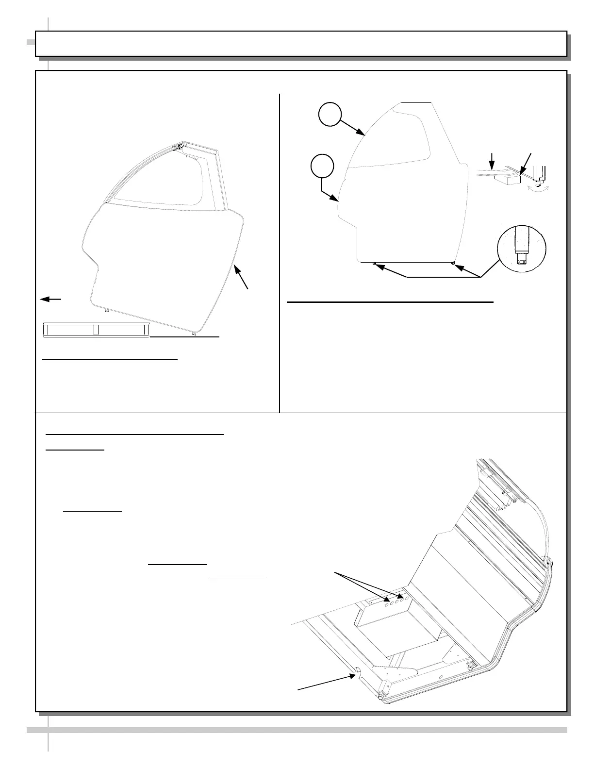
1. Remove Unit From Skid
Caution: case must always remain supported or
center of gravity will allow case to fall. Slide unit
to rear of skid and tip backward off skid.
3. Remote Electrical Connections:
Model G24F: Field wiring hook-up / electrical access locations are shown in
the illustration below.
220V Single Phase Leads or Cord with Nema Plugs provided.
See SERIAL LABEL LOCATION & INFORMATION LISTED / TECH
INFO & SERVICE for more detailed information.
Model G12F: Field wiring hook-up / electrical access locations are at
opposite end than that shown below.
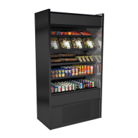
Installation: Units shown may not depict an exact representation of your particular unit being installed.
Slide
Skid
Out
Support
required
to prevent
tipping.
2. Case Aligning, Adjusting and Sealing
For Service Glass to align properly, case must be
level and plumb. Adjust feet accordingly (see
illustration above).
Caution! These units MUST BE sealed to the
floor to maintain conformance to NSF®
equipment mounting standards.
Align multiple units (as shown above with balloons
A and B).
A
B
Pry
Bar
Block
Wireway through Rear Grille
Model G24F: Field Wiring Hookup into
Electrical Box Model G12F
: Field Wiring
Hookup is at opposite end.
Case
Front