7
INSTALLATION, CONTINUED
3. Electrical Connections (Remote Cases)
Field wiring connection / electrical access location
is at customer-left side of case.
Single phase leads are provided.
Connection
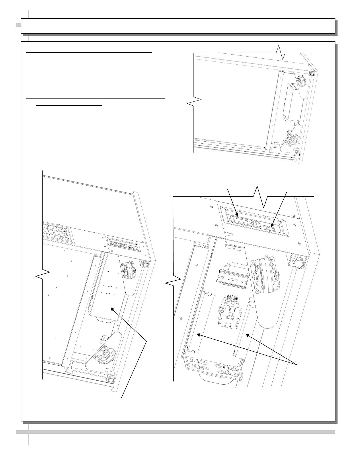
4. Connections/Controller/Main Power Switch
(Self-Contained Units)
Controller/Ballast box is at customer rear.
See illustrations below.
Below illustrations show layout of controller,
ballasts, main power switch, terminal block, etc.
after removal of controller/ballast box cover.
HMO7536R Underside View With
Controller/Ballast Box Cover Intact
HMO7536R Underside With
Controller/Ballast Box Cover Removed
Controller
Main Power
Switch
Ballasts