H
Guiding the way
This guide summarizes some of
the common features, functions,
button pushing and menus of the
Consolidated Operating Room
Equipment (CORE) 2 console.
The CORE 2 console powers a
variety of devices, including:
• Small and large bone drills,
saws and drivers
• Small and large joint shavers
• ENT shavers
• Various foot pedals
• Bone mill
• Irrigation
Collectively, the console and
its related accessories are
intended for:
• For use in a variety of
surgical procedures, including
orthopaedic, dental, ENT,
neuro, spine, and endoscopic
applications.
• Cut, drill, ream, decorticate,
shape and smooth bone, bone
cement and teeth
• Place or cut screws, metal,
wires, pins and other xation
devices
Unless specied, use
only with Stryker-approved
equipment and keep console
outside the sterile eld. Among
other safety directives, adhere to
recommended duty cycles, and
carefully select motor settings
and irrigation ow rate for the
attachments and procedure at
hand. This user guide is not
intended to replace Instructions
for Use documents. It is
purely provided to summarize
commonly used features.
For a complete list of
warnings and cautions,
operational details,
troubleshooting tips, cleaning
protocols and duty cycles, please
consult the current Stryker CORE
2 console Instructions for Use
(IFU Ref 5400-052-700-EN), and
IFUs for any Stryker drill motor,
foot/hand switch, attachment or
other accessory you connect to
the CORE 2 console.
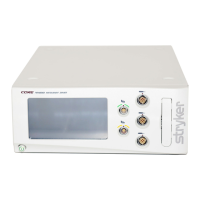
Key
features
A Power button
B 7” touch screen with
24-bit color and 170°
wide viewing angle
C Port illumination rings
(5) for constant, color-lit
visibility of matched
motors and foot pedals
D Stacking inserts (4)
I Pole bracket for irrigation
J Ethernet port
K USB port
L Specication label
M Equipotential lug
N Fuse holder
O Power receptacle
E Motor ports (3); runs
2 non-heavy duty handpieces
simultaneously. Port location
rened to provide more room
around the irrigation cassette.
F Foot pedal ports (2)
G Irrigation cassette port
with simple, one-step
insertion and removal
H Stacking feet (4)
P Internal audio with
distinct tones for actuation,
completion, reverse motor,
notications, errors and
prohibited actions
Q Passively cooled;
no fan, no moving parts
or associated noise
G
A
B
I
J
P
Q
N
K
L
M
O
D
E
C
F