EENN
1-38 2971-109-001 REV B www.stryker.com
Service
Pod assembly replacement (Continued)
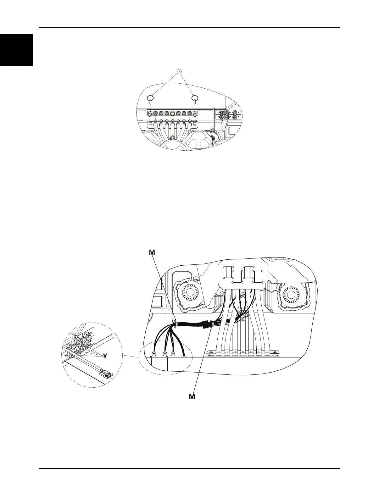
Figure 1-13: Retaining pins
7. Grasp both sides of the hose quick connection from the pod assembly and carefully pull outward toward the head
end of the support surface to disconnect from the foot box manifold.
8. Disconnect the four pod sensor hoses (Y) (1 blue, 2 yellow, 4 green, and 5 orange) from the foot box. Push inward
on the coupling and pull outward on each of the hoses (Figure 1-14 on page 1-38).
Notes
• When handling the pod sensor hoses, do not bend or kink the hoses.
• Pay attention to the sensor hose position and insertion color and number labels.
• During re-install, make sure to insert the hose and once you hit a stop, continue pushing until you reach a hard
stop.
Figure 1-14: Pod sensor hoses and purse lock wire tie
9. Remove sensor hoses from the purse lock wire ties (M) (Figure 1-14 on page 1-38).
10. Reach under the pod assembly (C) from the patients right side near the middle to access the turn bladder and
disconnect the turn bladder quick disconnect. Repeat on the patient left side (Figure 1-15 on page 1-39).