20
/11.2015/G17D
A,-Gerät 201 291 351 381 451 561 431 551
Druckleitung 16 22 22 22 22 22 22 22
Flüssigkeitsleitung 16 16 16 16 16 22 16 16
AS-Gerät 271 401 511
Druckleitung 16 18 22
Flüssigkeitsleitung 16 16 22
*(123)
*(143)
85
EN
Refrigerant line connection (1 circuit) in mm
A unit
Pressure line
Liquid line
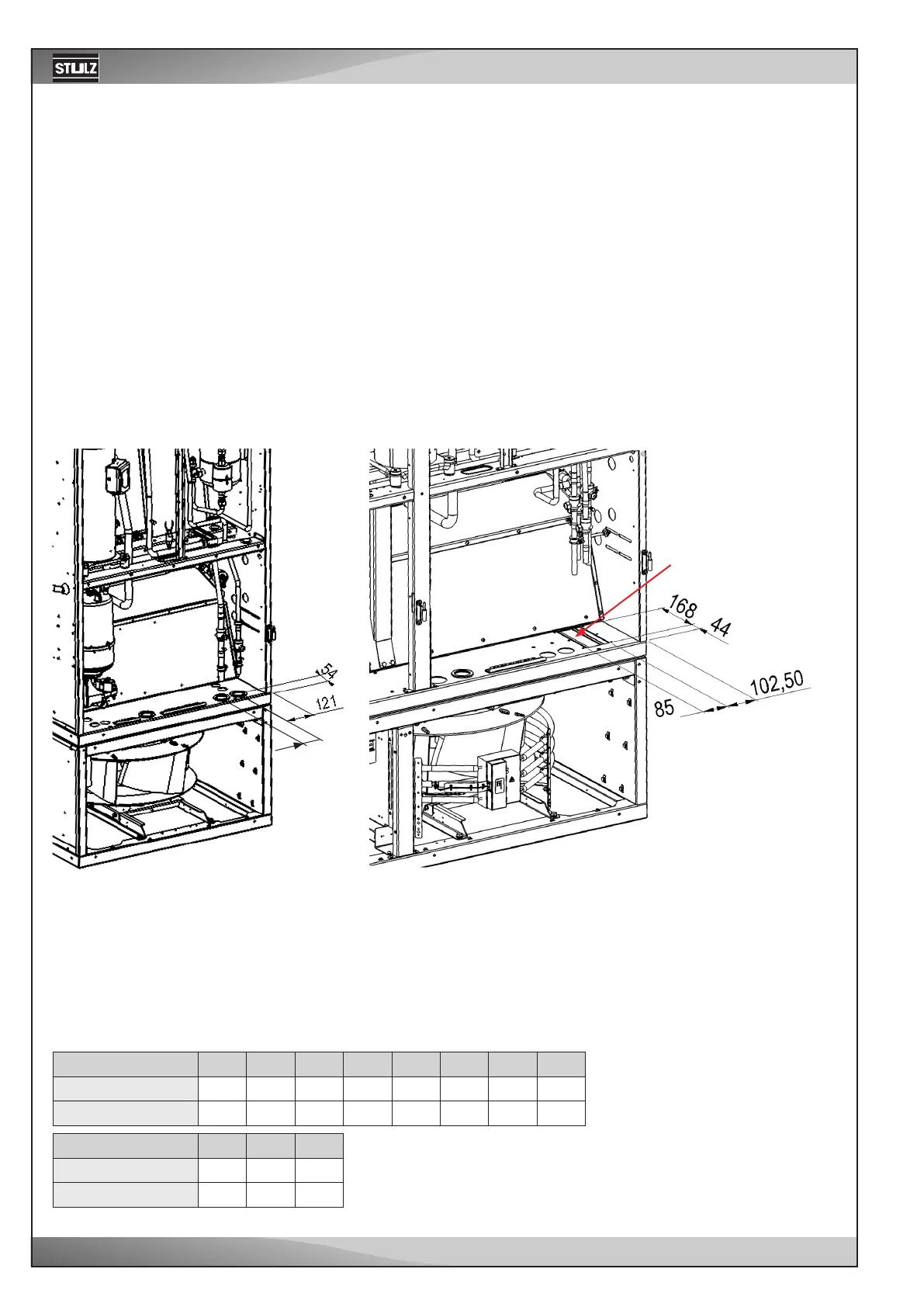
6.2 Connection of the piping
6.2.1 Refrigerant piping (A/AS units)
Pipe entrance area
for refrigerant lines
*distance from the exterior side of the side panel to the zone of introduction. This dimension is decisive if several
units are installed fitting exactly side by side.
AS unit
Pressure line
Liquid line
To design the piping between the A/C unit and the condenser follow the instructions in chapter "2. Refrigerant piping"
of document "General-DX". This document is available in the e-Stulz area.
6.2.1.2 Position of the refrigerant connections
6.2.1.1 Design
Size 1 Sizes 2 - 7
A/C units of the versions A and AS are equipped with an open refrigerant circuit. To close the circuit these units must
be connected to an external condenser.