2
X Z
Y
Z (min. 50)
Z (min. 800)
Z
(min. 50)
H
min
— H
max
Hmin — Hmax
[mm]
995 — 1045
895 — 945
795 — 845
695 — 745
595 — 645
495 — 545
355 — 405
270 — 320
EN/05.2017 © STULZ GmbH – all rights reserved
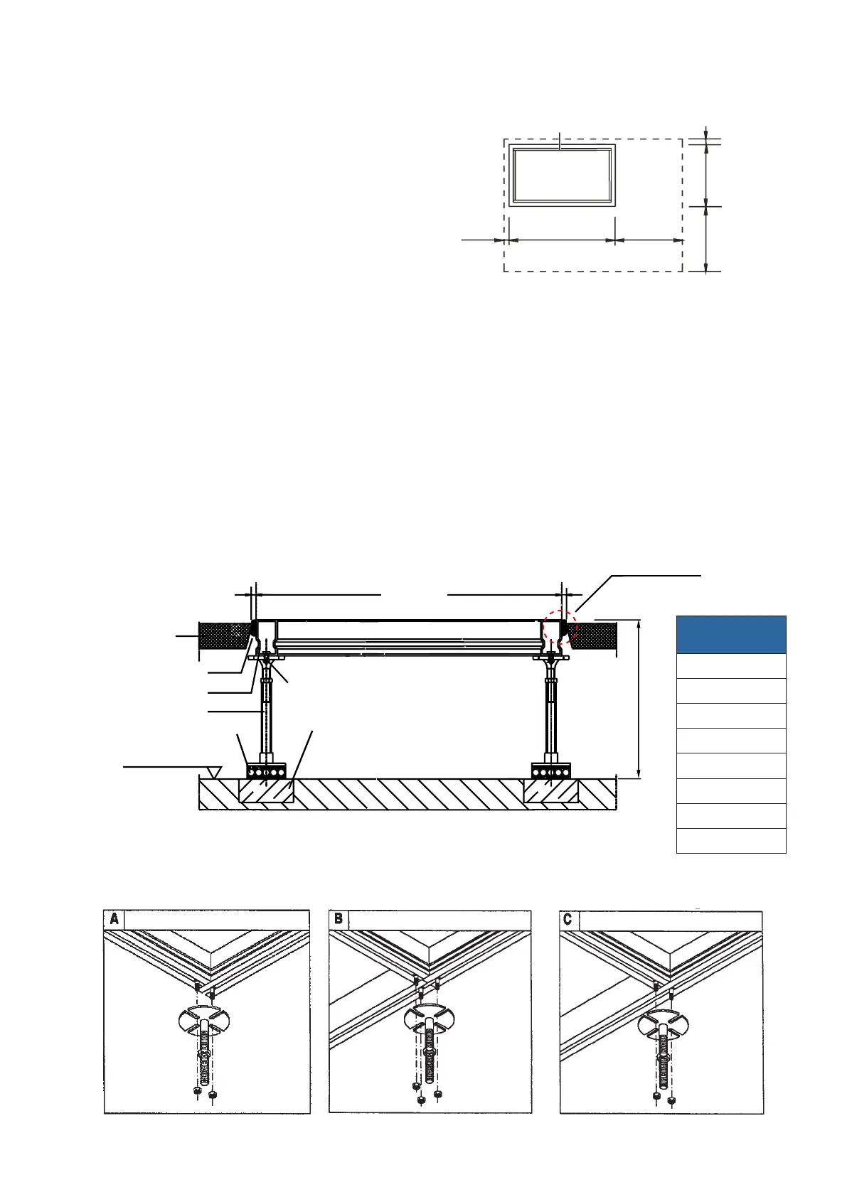
raised floor stand
Connecting the bars (View from below)
Angle Connection Butt Joint Cross Connection
Mounting
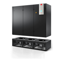
Raised floor stand
X/Y = Opening in raised floor
Z = Limit of distance
• Aconcretefoundationisrecommendedinthe
area of the raised floor supports.
• Iftheoorstandisplacednearawall,aminimum
distance of 50 mm must be respected. The gap
between wall and floor stand must be closed by
tin stripes.
• Choosethedimensionsoftheopeningsinthe
raised floor (X and Y) 10 mm longer than the
raised floor stand dimensions.
• Closethejointwithacontinuousseal.
• Theraisedoorcutting(notch)shouldat
least be 15° and must not have any contact
totheraisedoorstand,whichcouldresultin
bone-conduction.
• Installtheraisedoorsupportsonvibration
dampening material (Mafund plate) (do not screw
down the supports!).
• PriortoinstallationoftheA/Cunit,installthe
raised floor 7 mm higher than the raised floor
plates,asthemafundplatesarecompressedby
the weight of the A/C unit.
Raised floor connection
fordetails,seenextpage
Hammer head screw M8 30
Recommended concrete
foundations (no floor finish)
Raised floor
Raised floor stand
Continuous seal
Raised floor support
Mafund plate
Upper edge of
rough floor
Unit width
General design of the raised foor stand