42 EN/39B/06.2018 © STULZ SpA – all rights reserved
SAL
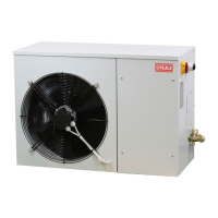
Outdoor part
Outdoor part (motor-condensing unit) must be positioned outside the shelter and connected to the
indoor unit by two refrigerant pipes. Position of motor-condensing unit and evaporating unit should
be chosen to minimize pipe distance between them. In any case equivalent length of each must not
be over 30 m for R407C.
• Check that there is enough space for easy application, installation and maintenance, both
inside and outside the shelter. Always observe the minimum spaces indicated in the drawings in
paragraph"5.3. Drawings".
• The outdoor unit must be installed with a minimum distance of 250 mm from the shelter wall,
to reach the designed air flow inside it and allow the connection of refrigerant pipes on the
connectors, located on the rear side.
• If possible, choose a position for the outdoor unit far from polluting agents and protected from
direct sun radiation, to ensure the highest efficiency of the system. Do not obstruct the air suction
and discharge area. Make sure that the unit cannot be covered by snow.
• Provide a secure fixing for the unit, if necessary with additional supports. In case of wall
installation, to support the motor-condensing unit, is available also a mounting kit as accessory
(ACTMKITSO1).
Free cooling module
The free cooling module must be installed between the indoor unit and the wall, which must have an
air opening to allow the external fresh air intake. Proceed in the following way:
1. Disassemble the air return grille in the rear panel of the internal unit.
2. Put the screws on the internal unit, leaving them loosened, as shown on the drawings in the
following page.
3. Embed the free cooling module on the rear part of the internal unit, fixing four screws, as shown
on the drawings in the following page.
4. Assemble the air return grille on the rear side of the free cooling module.
5. Connect the free cooling module to the internal unit through the 6 poles connector. The internal
unit automatically recognizes the connection with the free cooling module and configures itself
accordingly.
With free cooling module, two openings on the walls are necessary.
• Fresh air intake opening: it must be made according to the dimensions of the terminal adaptor
plates of connection ducts. In all the cases, this opening has to be protected by rainproof grilles
(accessory ACTGRxxSAL). Cut out dimensions are 515260 in SplitAir3 size 1 and 715310 in
SplitAir3 size 2.
• Exhaust air discharge opening. It should be placed in a position which allows a good air circulation
during free cooling, avoiding short circuits between fresh and exhaust air. An overpressure damper
must be installed on this opening, so that internal air cannot go out from it during cooling operation
(accessory ACTODALFCL).
After making cuts on the shelter panels, suitably insulate them against water infiltration.
To connect the fresh air intake of the indoor unit to the opening on the shelter wall, air ducts are
required. These ducts are available as options, with the following codes:
• ACTDVINSAL: rectangular section duct for vertical indoor unit;
• ACTSHDROSALxx: flexible round section double duct kit for horizontal indoor unit.
If no-one of these accessories is ordered, suitable ducts must be provided.