48 EN/39B/06.2018 © STULZ SpA – all rights reserved
SAL
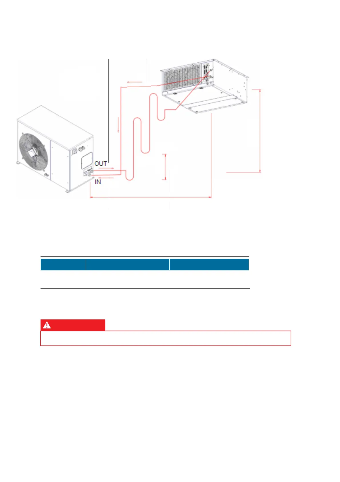
Connectors on the condensing unit Connectors on the evaporating unit
Liquid/gas pipeline Refrigerant tap 1/2", connection 1/4" Refrigerant joint - 1/2" SAE / ODS ø12
Gas pipeline Refrigerant tap 3/4", connection 1/4" Refrigerant joint - 3/4 SAE / ODS ø18
Closing the circuit and testing the seal
ATTENTION
Do not open refrigerant taps of the condensing unit before closing the circuit and testing the seal.
On gas suction line: open refrigerant cap of the evaporating unit and connect with the IN refrigerant
tap of motor-condensing unit. On liquid line: open refrigerant cap of the evaporating unit and
connect with the OUT refrigerant tap of motor-condensing unit. Positions of refrigerant connectors
on evaporating and motor-condensing units are shown in the drawings in the previous pages.
After connecting the refrigerant lines, connect a suitable vacuum pump (complete with vacuum
meter) to both the refrigerant taps of the motor-condensing unit. Evacuate the air inside the lines.
Value to be reached is 0.3 mbar absolute. Check after 3 hours if pressure within the pipes has risen
over 1.3 mbar absolute. If so, this means that there is a leakage on connection pipes, which have to
be repaired before proceeding with the next phase.
A
NOTE:
Max equivalent length for refrig-
erant line A + B < 30 m
B max < 10 m
Vertical distance
Gas pipeline
(Sloping 1%)
Gas pipeline
(Sloping 1%)
Liquid/gas
pipeline
5 m max vertical distance
between two siphons