51 © STULZ SpA . – all rights reserved EN/39B/06.2018
SAL
The conditioning system must be electrically connected in compliance with the regulations at
paragraph "Introduction" and national regulations for technical systems.
• Check that supply voltage and frequency are compatible with those for the unit.
• Interrupt both main power and auxiliary power before working on the system.
• Select connection cables (not supplied) according to EN602041 Standards.
• Check that power cables are installed with a sufficient distance from alarm cables, from the
network connection cable and from the master-slave connection cable.
• Install a disconnect switch (in overvoltage category III) on the main power lines and another
differential switch if necessary, please refer to the electrical diagram in manual part 2.
• Install an omni-pole automatic switch on the 48 VDC power supply lines, and another differential
switch if necessary.
• To make electrical connection of power supply, use cables with section suitable to the power
absorbed by the users (check interconnection diagram on manual part 2). These cables must be
compliant with current standards.
• Verify carefully the polarities of DC power supply, according to the wiring diagram on manual part 2.
• For 3-phase scroll compressors: take care of correct phase sequence after the connection
of the main power supply. The sequence is important for the correct sense of rotation of the
3-phase Scroll compressor. A loud noise coming from the compressor means it's turning in the
wrong direction. If this continues for a few hours, it will overheat and irreparably damage the
compressor. Correct compressor operation can be easily checked by measuring the temperature
at the condenser outlet. If this temperature is noticeably higher than the external temperature, the
compressors is working correctly. Otherwise, the compressor is turning in the wrong direction and
the phase sequence must be changed.
DANGER
The inobservance of these points can provoke damages or malfunction of components and
warranty shall become forthwith void.
For use of leakage-current (FI) circuit breakers, EN 50178 5.2.11.2 must be taken into
account. Only type B pulse-current FI circuit breakers are permitted. FI circuit breakers do not
provide protection against bodily harm during operation of the unit or frequency converters.
Follow instructions below:
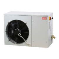
1. The electrical box of the evaporating unit can be accessed removing its panel located in the
bottom side near the rear of the unit. The electrical box of the condensing unit can be accessed
removing its upper panel(SAL 40/60/80) or front upper panel (SAL A0/A2/A4).
2. Connect the supply cable, from the external to the internal unit, into the electric panel of the
condensing unit, in the appropriate position (indicated in the electrical diagram of the unit in
manual part 2), and then this cable must be routed out of the condensing unit through a hole in
the same plate which is used to put the power supply cables. The cable must be taken inside
the room and brought into the evaporating unit, in the plate located on the rear side of the
evaporating unit, and connected to the electrical panel, as shown in the electrical diagrams.
Then connect main power supply to the condensing unit using a cable suitable to the current
absorbed by the condenser unit, indicated in technical data sheets in paragraph"Technical data".
For kind and section of this cable, please refer to the interconnection diagram in manual part 2.
ATTENTION
Provide proper sealing to the hole in cabinet wall for this cable, to prevent any water (rain)
infiltration.