52 EN/39B/06.2018 © STULZ SpA – all rights reserved
SAL
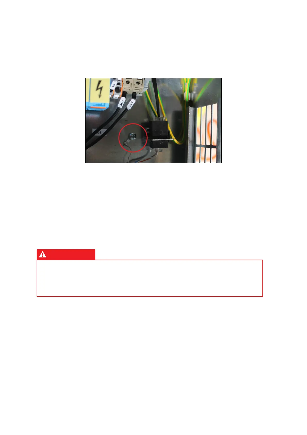
3. Besides the power supply cables, there is a communication cable which has to be connected
from evaporating to the condensing unit, as shown in the electrical diagram in manual part 2.
The connecting cable is a pin-to-pin cable with RJ11 plug and it's not supplied with the unit, but
available as STULZ accessory ACTSEQCxx. To ground shielded cables, if any, use the insert
near the connector of the outdoor unit (see image below).
4. Connect emergency 48 VDC power supply cables directly to the internal unit, passing them
through the two holes in the plate on the rear of the evaporating unit.
5. The following connectors are placed on connection plate located outside the evaporating unit:
• Connectors for digital output (alarms), analogue input (humidity probes) and digital input
(customer's external devices) signals connected to the electronic control board. All digital
output signals are voltage-free type, with the following rating for contacts: maximum allowed
voltage = 24V AC / 48V DC, maximum allowed current = 1A. All digital inputs require a
voltage-free signal from external devices eventually connected to them. I/O signal connectors
C1 and C2 are screw type.
• Phone connectors for key-pad and LAN sequencing.
ATTENTION
All the devices connected to the digital outputs and analogic inputs of the controller, must
be connected to a SELV type power source (voltage limit 42Vdc/ac). The digital inputs of the
controller must be connected to voltage-free contacts.
Please refer to use and maintenance manual part 2 for more information.