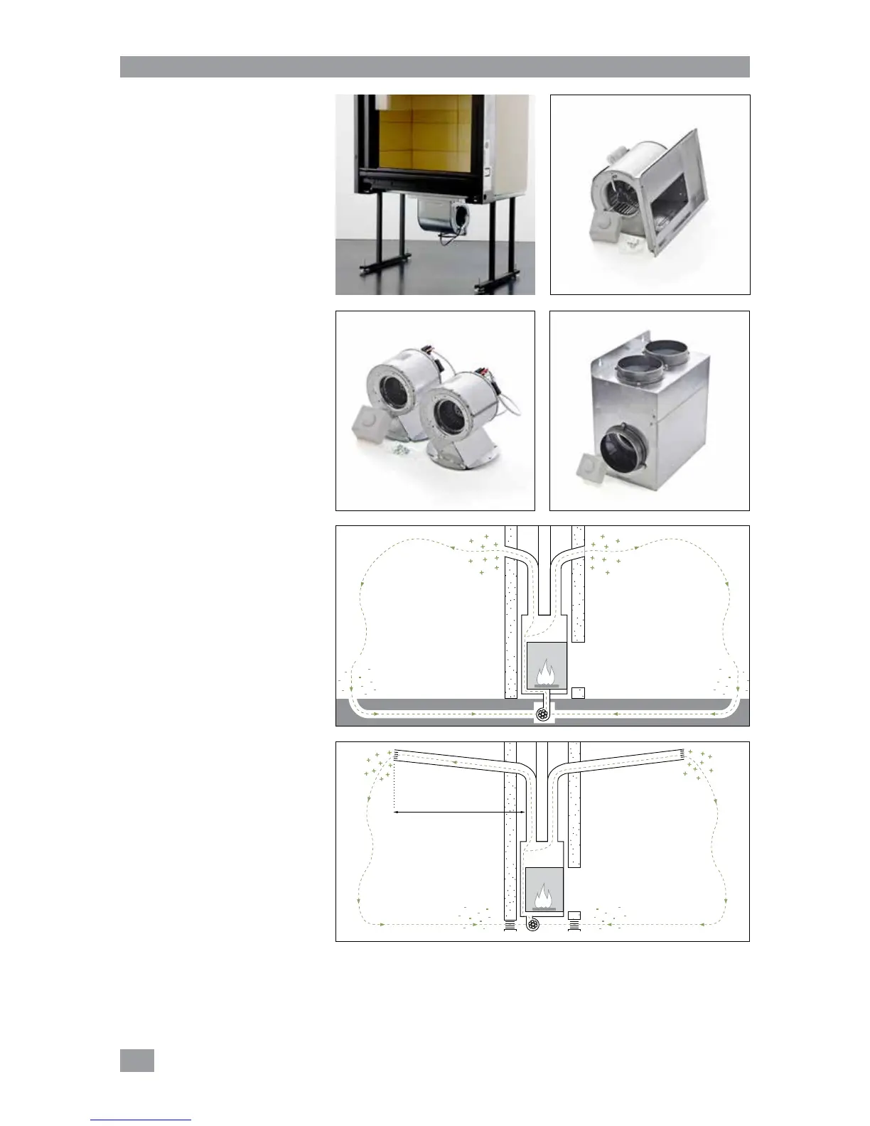
Types of ventilation unit
Stûv provides the option of three
different ventilation kits:
– 600 m³/h ventilation unit to be
installed under the stove from
inside the combustion chamber
[photos1&2]
Please note that this accessory is
not compatible with the models
21/45 and 21/65C,
– 2 fans to be installed laterally or at
the back (2 x 200 m³/h) [photo 3],
– Independent ventilation unit placed
at a distance (600 m³/h) [photo 4].
The duct should ideally come out
opposite the fan’s inlet. Leave
sufficient space (minimum 10 cm) to
facilitate air circulation.
Please note !
The fans supplied by Stûv are
designed to direct room air and not to
be installed in the hot air circuit at the
stove's outlet.
2 ways of creating an air circuit :
– install ducts in the stove's inlet to
draw in room air distant from the
stove [diagram5] or even from
another room in the house. For
this configuration, it is imperative
to use a fan in a water-tight case
[VENT21600EXT – photo4].
– install the ducts in the stove's outlet
to carry hot air further (max.3m)
even to an adjacent room
[diagram6].
In the both cases, a circulation of
air is created : the air reheated by
the stove moves towards the areas
from where the room air was drawn
(depression zone), ensuring a constant
temperature.
Whatever the air circuit planned
around the stove, please note the
local and national regulations in force
for this kind of installation.
Forced convection