Electronic Control System
Wine Storage
Wine Storage
(400-
(400-
2
2
)
)
Series
Series
3-24
#3758410 - Revision C - May, 2014
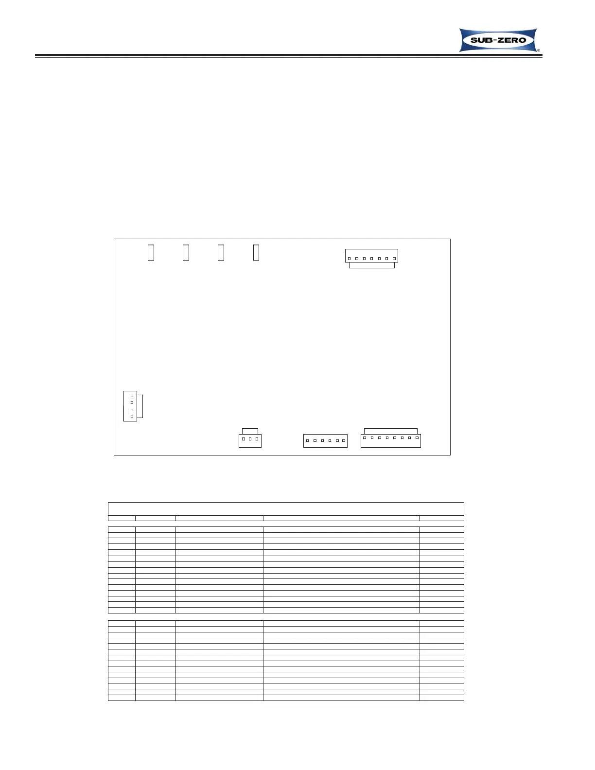
Figure 3-43. Main Control Board Layout
Figure 3-44. Control Board Summary Table
MODEL 427-2 REFRIGERATOR SECTION
CONTROL BOARD LAYOUT AND SUMMARY TABLE
Electrical connection points on the control board are labeled alphanumerically. These labels correspond with the
alphanumeric summary table, located on the wiring diagram. By referencing the summary table, it is possible to
identify which components are connected at which points on the main control board. Below is a layout diagram of
the control board, and a copy of the summary table. (See Figures 3-43 & 3-44)
NOTE: All components on the control board are non-replaceable. If a problem with the control board is identified,
the complete control board must be replaced.
NOTE: There is also a small PC board in the control panel assembly (Not Shown). All components in the control
panel assembly are non-replaceable. If a problem with the control panel is identified, the complete control panel
assembly must be replaced.
CIRCUIT
LOW VOLTAGE THERMISTOR CIRCUITS
120 VOLT CIRCUITS
TERMINAL
MAIN CONTROL BOARD SUMMARY
DESCRIPTION
WHITE
PURPLE
COLOR
BLACK
BLUE
RED
YELLOW
ORANGE
ORANGE
BLUE/YELLOW
BLACK
WHITE
YELLOW
BLUE/WHITE
BLUE/YELLOW
RED
BLUE
GROUND FOR DISPLAY BOARD POWER SUPPLY
12VDC POWER SUPPLY FOR DISPLAY BOARD
GROUND FOR DISPLAY BOARD POWER SUPPLY
SERIAL DATE TRANSMIT
SERIAL DATA RECEIVE
12VDC POWER SUPPLY FOR DISPLAY BOARD
SENSES EVAPORATOR TEMPERATURE
SENSES REFER CABINET TEMPERATURE
SENSES IF DRAWER OPEN
POWERS COMPRESSOR AND CONDENSER FAN
POWERS DEFROST CIRCUIT AND FILL TUBE HEATER
SENSES EVAPORATOR TEMPERATURE
POWERS EVAPORATOR FAN
POWER INTO BOARD
NEUTRAL INTO BOARD
FUNCTION
POWERS LIGHTS
NOT USED
DRAWER LIGHT SENSE
NOT USED
NOT USED
NOT USED
NEUTRAL
NOT USED
EVAPORATOR FAN
DEFROST HEATER
COMPRESSOR
POWER IN
LIGHTS
NOT USED
NOT USED
NOT USED
NOT USED
REFRIGERATOR COMPARTMENT
DISPLAY WIRING
EVAPORATOR
DISPLAY WIRING
DISPLAY WIRING
DISPLAY WIRING
DISPLAY WIRING
EVAPORATOR
NOT USED
NOT USED
NOT USED
DISPLAY WIRING
UPPER
EVAP
EVAP
DISPLAY
DISPLAY
DISPLAY
DISPLAY
DISPLAY
DISPLAY
UPR
LIGHTS
FAN 1
DEFROST
COMPRESSOR
L1
LN
J5-3,4
J3-3
P3
P4
P2
P1
J3-1
J3-2
J3-6
J3-5
J3-4
J2-1
J3-7
J5-1,2
J2-4
J2-3
J2-2
J4-5
J5-5,6
J5-7
J6-2
J6-1
J5-8
J4-2
J4-1
J6-3
J4-4
J4-3
J4-6