Meters and gauges
NOTE
Some of the meters and gauges on the
combination meter use liquid-crystal
displays. You will find their indications
hard to see if y ou wear polarized
glasses.
& Combination meter illumina-
tion
When the ignition switch is turned to the
“ON” position, various parts of the combi-
nation meter will illuminate in the following
sequence.
1. Warning lights, indicator lights, meter
needles, gauge needles and liquid crystal
display illuminate.
2. Meter and gau ge indic ations each
show MAX position.
3. Meter and gau ge indic ations each
show MIN position.
4. Regular illumination (for driving) be-
gins.
& Canceling the function for
meter/gauge needle move-
ment upon turning on the
ignition switch
It is possible to activate or deactivate the
movement of th e meter needles and
gauge needles that takes place when the
ignition switch is turned to the “ON”
position. To change the setting, perform
the following procedure.
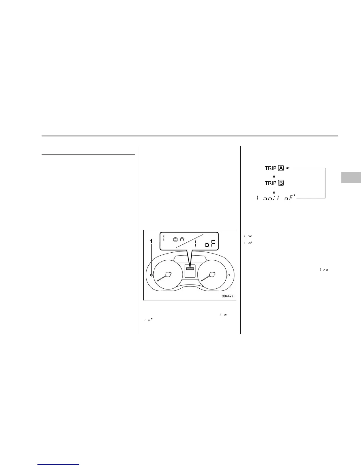
! Type A combination meter
1. Turn the ignition switch to the “LOCK”/
“OFF” or “ACC” position.
1) Trip knob
2. Press the trip knob to show “ ” or
“
” on the trip meter display.
The display can be switched as shown in
the following sequence by pressing the
trip knob.
*: They cannot be displayed when the
ignition switch is in the “ON” position.
To change the current setting, press the
trip knob for at least 2 seconds.
: Activated
: Deactivated
NOTE
. Your vehi cle’s initial movement
setting of the meter/gauge needles
has been set for activation “
” at
the time of shipment from the factory.
. It is not possible to change the initial
movement setting of the meter/gauge
needles when the ignition switch is in
the “ON” position. Change the setting
when the ignition switch is in the
“LOCK”/“OFF” or “ACC” position.
Instruments and controls/Meters and gauges
– CONTINUED –
3-9















 To Next Page