Section 2
DESCRIPTION
9
Fluid flows from the bottom of the receiver/sump to
the thermal valve. The thermal valve is fully open
when the fluid temperature is below 170
_
F(77
_
C).
The fluid passes through the thermal valve, themain
filter and directly to the compressor unit where it lu-
bricates, cools and seals the rotors and the com-
pression chamber.
As the discharge temperature rises above 170
_
F
(77
_
C), due to the heat of compression, the thermal
valve begins to close and a portion of the fluid then
flows through the cooler. From the cooler the fluid
flows to the main filter and then on to the compres-
sor unit.
A portion of the fluid flowing to the compressor is
routed to the anti--friction bearings which support
the rotors inside the compressor unit. Prior to enter-
ing the compressor unit, this fluid is taken through
the fluid filter, thus assuring properly filtered lubri-
cant for bearing supply.
The fluid filter has a replacement element and an in-
tegral pressure bypass valve.A gauge on the instru-
ment panel shows red when the filter needs servic-
ing. This gauge has a pressure setting lower than
that of the bypass valve. The gauge should be
checked with compressor running at full system
pressure.
Water--cooled versions of the compressor have a
water--flow regulating valve (not shown) whichoper-
ates to conserve water during periods of varying
load on the compressor. This same valve automati-
cally shuts off the water supply when the compres-
sor is shut down. In addition, water--cooled models
have a water pressure switch to prevent operation
with inadequate water pressure.
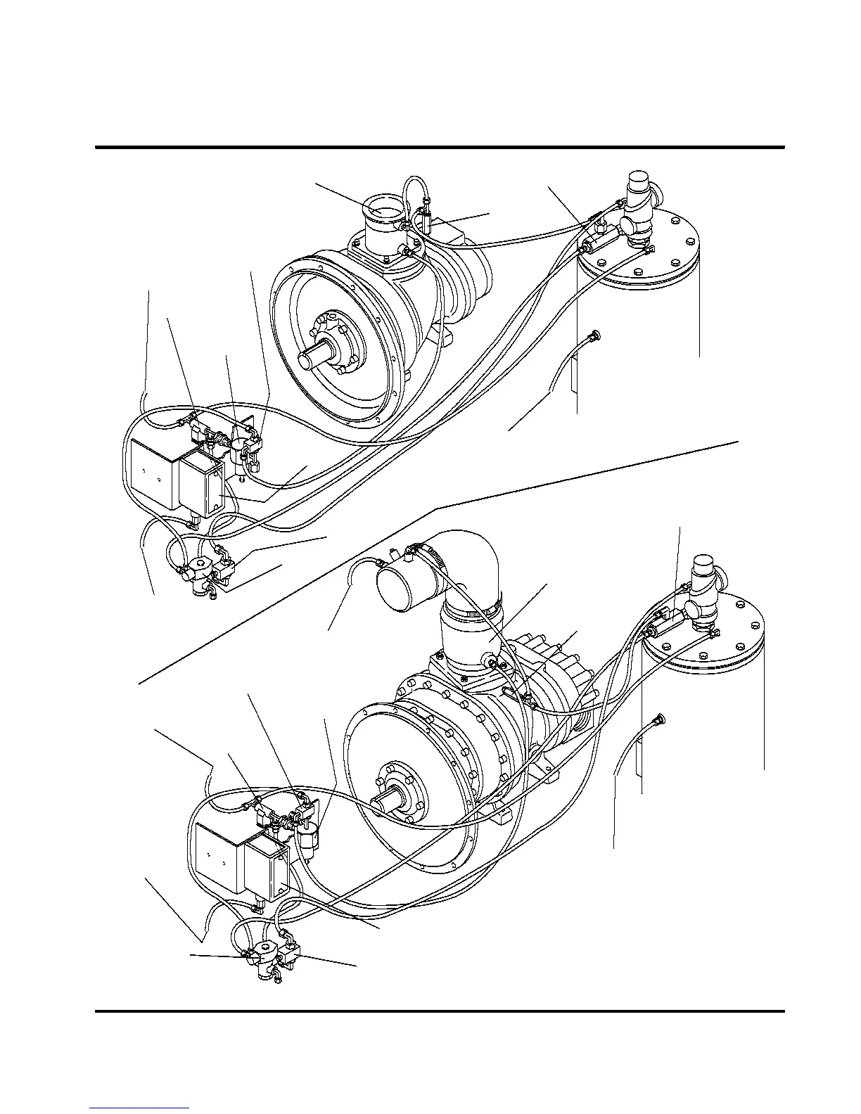
2.5 COMPRESSOR DISCHARGE SYSTEM, FUNC-
TIONAL DESCRIPTION
Refer t o F igur es 2 -- 3A and 2 -- 3B. T he c ompr es s or
unit discharges the compressed air/fluid mixture
into the combination receiver/sump.
The receiver has three basic functions:
1. It acts as a primary fluid separator.
2. Serves as the compressor fluid sump.
3. Houses the final fluid separator.
The compressed air/fluid mixture enters the receiv-
er and is directed against the internal baffle. The
direction of movement is changed and its velocity
significantly reduced, thus causing large droplets of
fluid to form and fall to the bottom of the receiver/
sump. The fractional percentage of fluid remaining
in the compressed air collects on the surface of the
separator element as the compressed air flows
through the separator. A return line (or scavenge
tube) leads from the bottom of the separator ele-
ment to the inlet region of the compressor unit. Fluid
collecting on the bottom of the separator is returned
to the compressor by a pressure differential be-
tween the receiver and the compressor inlet. A visu-
al sight glass is located on the return line to observe
this fluid flow. There is also an orifice in this return
line (protected by a strainer) to assure proper flow.
This separation will reduce the fluid carry--over to
less than 2 ppm (parts per million). A gauge, located
on the instrument panel, shows red if abnormal
pressure drop through the separator develops. At
this time, separator element replacement is neces-
sary. This gauge must be checked with the com-
pressor running fully loaded.
A minimum pressure/check valve, located down-
stream from the separator, assures a minimum re-
ceiver pressure of 55 psig (3.8 bar) during loaded
conditions. This pressure is necessary for proper
air/fluid separation and proper fluid circulation.
A terminal check valve is incorporated into the mini-
mum pressure/check valve to prevent compressed
air in the service line from bleeding back into the re-
ceiver on shutdown and during operation of the
compressor in an unloaded condition.
A pressure relief valve (located on the wet side of
the separator) isset to open if thesump pressureex-
ceeds the sump tank rating. A temperature switch
will shut down the compressor if the discharge tem-
perature reaches 235
_
F(113
_
C).
WARNING
!
DO NOT remove caps, plugs, and/or other com-
ponents when compressor is running or pressur-
ized.
Stop compressor and relieve all internal pressure
before doing so.
Fluid is added to the sump via a capped fluid filler
opening, placed low on the tank to preventoverfilling
of the sump. A sight glass enables the operator to
visually monitor the sump fluid level.
2.6 CONTROL SYSTEM, FUNCTIONAL DE-
SCRIPTION- STANDARD ELECTRO-MECHANI-
CAL
Refer t o F igur e 2 -- 4. T he pur pos e of t he c ompr es s or
Control System is to regulate the compressor air in-
take to match the amount of compressed air being
used. At approximately 10 psig (0.7 bar) air line
over--pressure,the controlsystem willautomatically
blow down the compressor and greatly reduce the
unload power consumption. The Control System
consists of an
inlet valve
, (located on the compres-
sor air inlet),
blowdown valve
,
solenoid valve
,
pressure switch
, and a
pressure regulator
.The
functional descriptions of the Control System are
given below in four distinct phases of compressor
operation. The following guidelines apply to all
LS--10 Series compressors. For explanatory pur-
poses this description will apply to a compressor
with an operating pressure range of 115 to 125 psig
(7.9 to 8.6 bar). A compressor with any other pres-
sure range would operate in the same manner ex-
 Loading...