Section 5
OPERATION- ELECTRO-MECHANICAL
27
5.1 GENERAL INTRODUCTION- STANDARD ELEC-
TRO-MECHANICAL
While Sullair has built into this compressor a com-
prehensive array of controls and indicators to
assure you that it is operating properly, you will
want to recognize and interpret the reading which
will call for service or indicate the beginning of a
malfunction. Before starting your Sullair compres-
sor, read this section thoroughly and familiarize
yourself with the controls and indicators - their pur-
pose, location and use.
EMERGENCY STOP SWITCH
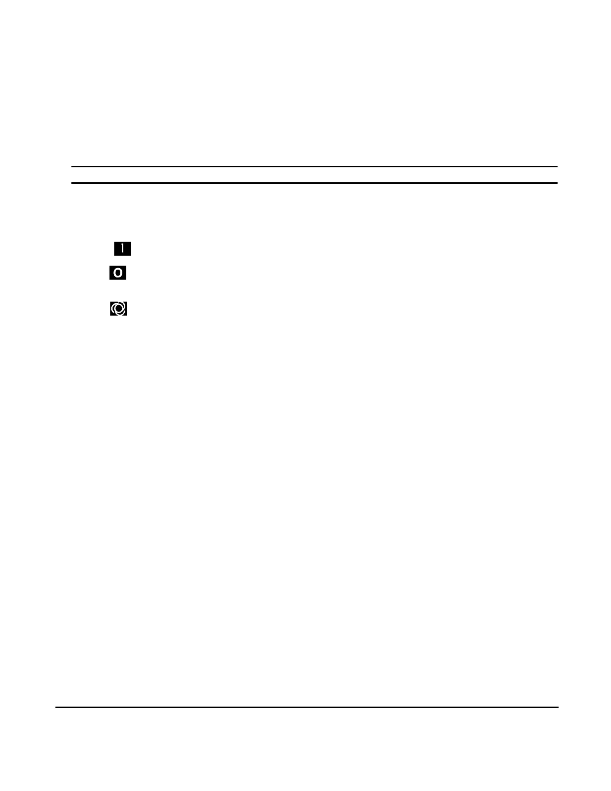
START " " PAD
STOP " " PAD
AUTO " " PAD
HOURMETER
LINE PRESSURE GAUGE
SUMP PRESSURE GAUGE
DISCHARGE TEMPERATURE GAUGE
AIR FILTER RESTRICTION GAUGE
FLUID FILTER MAINTENANCE GAUGE
SEPARATOR MAINTENANCE GAUGE
Pushing in this switch, found adjacent to the controller, cuts all
AC outputs from the latter and de-energizes the starter. A fault
message (E STOP) is displayed by the Supervisor Controller
until the button is pulled out and the “O” pad is depressed.
Depress to turn the compressor ON.
Depress to turn the compressor OFF and reset the common
fault circuit.
To select between continuous (HAND) operation and automat-
ic stop/start (AUTO) operation. Shuts off compressor auto-
matically after the compressor runs unloaded for a specified
time (ranging from 3-60 minutes [T1]). Restarts compressor
when the pressure switch closes to the load setting. Dual con-
trol is enabled by pressing the “AUTO” pad.
Records cumulative hours of compressor operation; useful for
planning and logging service schedules.
Continually monitors service line air pressure. It is located on
dry side of receiver downstream from check valve.
Continually monitors receiver/sump pressure at various load
and/or unloaded conditions.
Monitors temperature of the air leaving the compressor unit.
For both air and water-cooled compressors, the normal read-
ing should be approximately 180°F to 205°F (82°C to 96°C).
Indicates when the air filter element change is required. The
gauge shows the red zone when drop through the filter is
excessive. The compressor must be running full load for an
accurate indication.
Indicates when a fluid filter element change is required. It
shows red when the pressure drop through the filter is exces-
sive.
Indicates when separator element change is required. Shows
red when the pressure drop through the filter is excessive.
The compressor must be running full load for an accurate indi-
cation.
5.2 PURPOSE OF CONTROLS- STANDARD ELECTRO-MECHANICAL
CONTROL OR INDICATOR PURPOSE
 Loading...

