Section 7
MAINTENANCE
36
with lock washers through the holes in the hubs and
element. Torque these bolts as shown in Table 1-
Installation Data.
DO NOT substitute the ferry head bolts supplied
with the coupling.
After tightening the bolts, tighten the set screws and
remove the hose clamp form the flexible element.
Check the coupling gap as listed in Table 1-
Installation Data, and shown in Figure 7-6. At this
time, the coupling is ready for operation.
DRIVE COUPLING DISASSEMBLY AND
REMOVAL
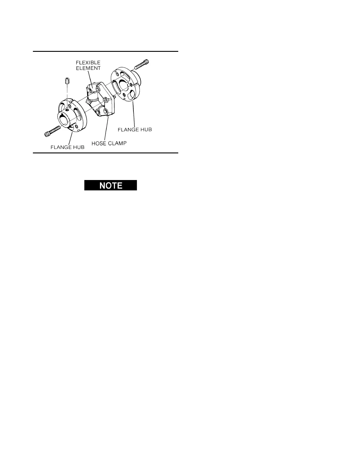
Refer to Figure 7-7. Disassembly and removal of
the drive coupling is done in the following manner:
1. Place a suitably sized radiator hose clamp over
the flexible element as show in Figure 7-7 and
tighten sufficiently to compress the rubber.
2. Remove the ferry head bolts from the hubs and
element.
3. Rotate the element until the studs clear the hubs.
4. Remove the element from the hubs with the hose
clamp still in place.
5. Loosen the shaft setscrews and remove the
hubs.
Figure 7-7 Drive Coupling
 Loading...

