2: Description ShopTek™ ST4, ST5, ST7, ST11, ST15 Three-phase 60 Hz User Manual
88292018-236 R00
14 Subject to EAR, ECCN EAR99 and related export control restrictions.
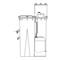
2.3 Compressor cooling and
lubrication system—functional
description
Refer to Figure 2-3 and Figure 2-4. The cooling and lubri-
cation system consists of a fan, fan motor, aftercooler
(
ST11/ST15 only) / fluid cooler, full flow fluid filter, thermal
valve, interconnecting hoses and separator tube.
The pressure in the separator tube starts the fluid flow by
for
cing the fluid from the high pressure area of the tube to
an area of lower pressure in the compressor unit. Fluid
flows from the bottom of the separator/tube to the thermal
valve that is fully open when the fluid temperature is
below 185°F (85°C) [195°F (91°C) for pressures rated
above 150 psig]. The fluid passes through the thermal
valve, the
fluid filter, and directly to the compressor where
it lubricates, cools and seals the rotors, and the compres-
sion chamber.
As the discharge temperature rises above 185°F (85°C)
[19
5°F (91°C) for pressures rated above 150 psig], due
to
the heat of compression, the thermal valve begins to
adjust and a portion of the fluid then flows through the
cooler. From the cooler the fluid flows to the fluid filter
and on to the compressor. A portion of the fluid flow to
the compressor is routed to the anti-friction bearings
which support the compressor rotors.
The fluid filter must be replaced. Refer to Section 3.4:
Lubrication change recommendations
and fluid filter and
separator maintenance on p
age 22.
2.4 Compressor discharge system—
functional description
Refer to Figure 2-3 and Figure 2-4. The compressor dis-
charges the compressed air/fluid mixtur
e into the separa-
tor/tube. The separator/tube has three basic functions:
• It acts as a primary fluid separator.
•
Serves as the compressor fluid sump.
• Houses the final fluid separator.
The compressed air/fluid mixture enters the separator/
tube
and flows through an internal baffle system that
changes the flow’s direction and velocity, which causes
most of the fluid to fall to the bottom of the separator
tube. A small amount of fluid remaining in the com-
pressed air collects on the surface of the separator ele-
ment as the air flows through the separator.
A return line (or scavenge tube) leads from the dry side of
the
separator tube to the medium pressure region. Scav-
enged fluid is returned by a pressure differential between
the sep
arator tube and compressor.
The separator system reduces the fluid car
ry-over to less
than 2 ppm at nominal rated pressures.
The controller will shut down the
compressor if the dis-
charge temperature reaches 235°F (113°C).
A minimum pressure/check valve loc
ated downstream
from the separator maintains the separator tube pressure
at 50 psig (3.4 bar) during load conditions. This pressure
leve
l is necessary for proper air/fluid separation and suffi-
cient fluid circulation.
A terminal check valve is a sub-component of the mini-
mum pressure/check valve that prevents compressed air
in th
e service line from back-flowing into the separator
tube on shutdown or when the compressor is operating in
an unload condition. Also, a pressure relief valve on the
compressor’s wet side opens if the separator tube pres-
sure exceeds its rating.
Add fluid to the separator tube through the capped fluid
fill
port. There is also a sight glass that enables the user
to check the separator tube fluid level. See Section 4.5:
Fluid level check on p
age 37.
WARNING
Stop the compressor and relieve all internal
pressure before removing caps, plugs, and/or
other components when the compressor is run-
ning or pressurized.
 Loading...