ShopTek™ ST4, ST5, ST7, ST11, ST15 Three-phase 60 Hz User Manual 4: Installation
88292018-236 R00
Subject to EAR, ECCN EAR99 and related export control restrictions. 37
4.3.1 Pipe sizing
Pipes should be sized as a minimum to match the dimen-
sions of the compressor’s discharge co
nnection. All piping
and fittings should be rated for the discharge pressure.
4.3.2 Auxiliary receiver tank
An auxiliary receiver tank should be installed in systems
where large demand fluctuations will occur.
4.3.3 Isolation valves
Install isolation valves where isolation of the compressor
from the service lines is required. These valves should
have drip legs that drain at an angle downward from the
base. A vent to the piping should be installed down-
stream of the compressor outlet connection.
When two compressors are installed to operate in parallel
with a comm
on receiver tank, an isolation valve and drain
trap for each compressor should be installed before the
common separator/sump.
4.3.4 Fluid containment
Compressors have a fluid containment pan to collect fluid
leaks or spills. The pan has a drain located on the front
side of the machine.
4.4 Belt check
Tension of drive belts should be checked upon installa-
tion and after ½ to 2 hours of run time. This is essential to
pr
oper performance of the compressor unit as well as to
ensure long belt life. In addition, belt tension should be
checked every 2000 hours and adjusted if necessary.
Refer to Section 6.8: Belt maintenance
on page 45 for
detailed instructions.
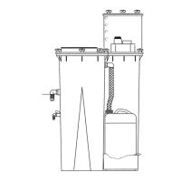
4.5 Fluid level check
The compressor is shipped fully charged with the proper
amount of fluid. However, it is necessary to check the fluid
level at the time of installation and during compressor oper-
ation. Check the fluid level by looking at the sight glass on
the sep
arator tube when the compressor is in the SHUT
DOWN MODE (fluid level may not be visible when operat-
ing). In this condition the sight glass should be completely
full. Add
fluid if the level is visible or if no fluid is visible at all.
4.6 Electrical preparation
Interior electrical wiring is installed at the factory.
Required customer wiring should be done by a qualified
electrician in compliance with OSHA, National Electric
Code and/or any applicable local electrical codes apply-
ing to isolation switches, fused disconnect
s, etc. Sullair
provides a wiring diagram for use by the installer. An
electrical check should be made to ensure that the first
start-up will be successful. The compressor and drive
should be properly grounded/earthed in accordance with
applicable codes, regulations, and requirements.
Feeder cables should be sized by the customer/electrical
con
tractor to ensure that the circuit is balanced and not
overloaded by other electrical equipment. The length of
wiring from a suitable electrical power source is critical
because voltage drops can adversely effect the perfor-
mance of the compressor. Cable sizes may v
ary consid-
erably so the mains terminals will
accept up to 120 mm
2
(4/0 awg) (75 kw) cable.
Feeder cable connections to incoming terminals L1-L2-
L3
should be tight and clean.
The applied voltage must conform to the motor and com-
pressor data plate ratings.
A starter hole is provided for an incoming power connec-
tion. If it is necessary to make a hole
in the control box in
a different location, care should be taken to not allow
metal shavings to enter the starter and other electrical
components within the box. If another hole is used, the
original hole must be blocked off with a sealed plug.
1. Check incoming voltage. The incoming volt-
ag
e must match the compressor’s wire rat-
ing/specifications.
2. Check motor starter and overload heater sizes.
3. Check all electrical connections for tightness.
NOTE
Compressors not equipped with a receiver tank
may need to have their response times adjusted.
Contact Sullair Customer Care for assistance.
WARNING
Energized internal components are a potentially
fatal shock hazard. Disconnect all power before
performing any work on the compressor’s elec-
trical system.
 Loading...