ShopTek™ ST4, ST5, ST7, ST11, ST15 Three-phase 60 Hz User Manual 6: Maintenance
88292018-236 R00
Subject to EAR, ECCN EAR99 and related export control restrictions. 45
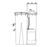
6.7.1 Separator element replacement
Refer to Figure 6-6 and Figure 6-7. Use the following pro-
cedure below to change the separator:
1. Loosen and remove the six (6) hex head
cap
screws (M12 x 45 mm) from the cover
plate.
2. Lift the cover plate from the separator tube.
3. Remove the separator element.
4. Inspect the separator tube for rust, contami-
nation, or damage.
5. Reinsert the separator elements into the
separator tube taking care not to dent the
element against the tank opening.
6. Install a new lubricated O-ring in the O-ring
groove on the underside of the separator/
tube cover.
7. Replace the cover plate, washers and cap-
screws. Torque to 28 ft·lbs. (38 N·m).
8. Clean the return line strainer before restart-
ing the compressor. Refer to Figure 6-1 and
Figure 6-2.
9. Check condition of grounding spring on lid,
ensure it is clean and provides good contact.
6.8 Belt maintenance
The correct drive belt tension is essential to ensure that
full motor power is transmitted to the compressor unit.
The belt tension is achieved by raising the compressor
unit which has the effect of increasing belt tension. Refer
to Figure 6-10 and Figure 6-11.
Belt tension must be re-adjusted ½ to 2 hours after a new
set
of belts are fitted. This will ensure that the belts have
completed their initial stretch. Subsequent to this, belt
tension needs to be checked and adjusted if necessary
every 2000 hours for the duration of the belt life.
There are two recommended methods for checking the
belt
tension. The test methods will be detailed as follows.
6.8.1 Belt tension measurement with
Optikrik tension meter
Refer to Figure 6-8. Follow instructions as follows:
1. Ensure the indicator arm is pushed down
pr
ior to starting.
2. Gently place the meter on the flat side of one
belt at the midpoint between the motor and
compressor unit pulleys.
3. Slowly press on the push pad. Avoid contact-
ing the meter with other fingers as this may
affect the reading.
4. Once a definite click is detected, immediately
release pressure and the indication arm will
remain in the measuring position.
5. Carefully lift the meter without moving indi-
cating arm.
6. Read the measurement at the exact point
where the top surface of the indicator arm
crosses the scale.
7. Rotate the motor pulley through at least one
complete revolution and measure the ten-
sion again, recording the results.
8. Repeat step 7 for a total of 3 measurements.
CAUTION
Relieve all pressure from the separator/sump
tank and all compressor lines.
Figure 6-8: Optikrik belt tension meter
 Loading...