24
Section 6
VARIABLE SPEED DRIVE
6.3 INSTALLATION
This variable speed AC drive has been properly
mounted, adjusted, and tested prior to shipment of
the compressor package. Inspect the unit to ensure
it was not damaged during shipment. The package
provides a terminal block for connection of three-
phase power and ground. Refer to the package
wiring diagram for specific connection information.
All internal wiring to the drive and motors has been
provided by the factory, in accordance with the
drive's requirements. Do not alter factory wiring. To
ensure proper wiring to the package, use the fol-
lowing guidelines:
• Use heat-resistant copper cables only,
+75°C or higher.
• The minimum input line cable and line fuses
must be sized in accordance with the rated
input current of the unit. See Table 6-1.
• Consistent with UL listing requirements, for
maximum protection of the variable speed
drive, use UL recognized fuses, type RK5.
• Suitable for circuits delivering fault currents
up to 100,000A.
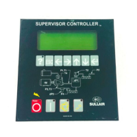
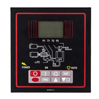
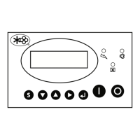
6.4 SUPERVISOR DISPLAY AND MENUS
Refer to Section 2 for a general description of the
Supervisor and its displays and adjustments. This
section addresses special functions applicable to
VSD packages.
6.4.1. VSD STATUS
This group of displays shows the performance of
the variable speed compressor package. The fol-
lowing may be used for evaluation of system per-
formance. The first four lines indicate real-time
conditions:
Capacity - Delivery in CFM.
Capacity % - Percent of full package capacity.
Power - Total package power in KW.
Power % - Percent of power at full capacity.
The next eight lines indicate recent longer-term
performance. See Section 6.4.2 for reset proce-
dure.
Capacity - Average delivery in CFM.
Capacity % - Average percent of full package
capacity.
Power - Average total package power in KW.
Power % - Average percent of power at full capac-
ity.
KCF - Running total of air delivered in thousands of
cubic feet.
Table 6-1: Cable and Fuse Sizes - 460V Ratings
_ UL recognized type RK.
_ Based on a maximum environment of 104°F (40°C).
hp Size (A) Fuse (A) Wire Size Wire Size
Power Ground
40 61 80 2 8
50 72 100 2 6
60 87 110 1 6
75 105 125 1/0 2
100 140 175 3/0 2
125 170 200 4/0 2
150 205 250 350MCM 1/0
200 261 350 2 x 250MCM 1/0
NOTE ON ELECTRICAL PREPARATION:
Interior electrical wiring is performed at the factory. Required customer wiring is minimal, but should be
done by a qualified electrician in compliance with OSHA, National Electrical Code, and/or any other appli-
cable State, Federal and local electrical codes concerning isolation switches, fused disconnects, etc.
Sullair provides a wiring diagram for use by the installer.
Customer must provide electrical supply power
disconnect within sight of machine.