Installation
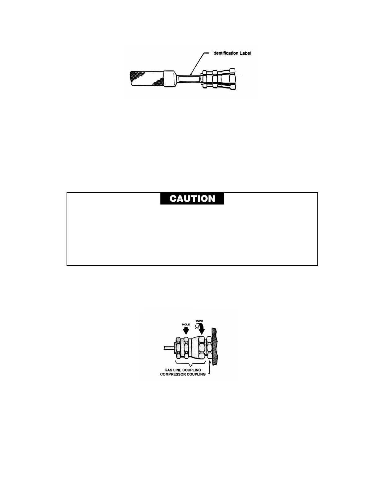
Figure 6 Attach Identification Label
2. Arrange the system components so that the gas lines will be protected from stress and
traffic. Observe the minimum bend radius of 180 mm (7") when routing gas lines. Provide
supports where needed.
3. Remove the dust caps from the compressor’s supply and return gas couplings.
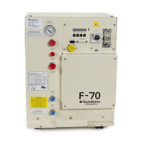
4. Connect the gas lines to the compressor’s high-pressure (supply) and low-pressure (return)
couplings. Use two wrenches to tighten the coupling. Torque all couplings to 47 ± 7 Nm (35
± 5 ft. lbs.) See Figure 7. Tighten each coupling before proceeding to the next one.
AVOID GAS LEAKS. Check the condition of the gasket seal on the male half of
each Aeroquip coupling. Be sure the gasket seal is in place and the sealing
surfaces on both the male and female halves are clean before connecting.
Replace the gasket seal if it is damaged or missing.
Keep the gas line couplings aligned when making or breaking a coupling
connection. Leaks can occur due to the weight of the gas line or due to a sharp
bend near the connection.
NOTE
Retain the dust caps and plugs to re-cover the couplings when they are not in
use. They protect the couplings from damage and prevent the entry of
Figure 7 Connect Gas Line to Compressor or Cold Head
5. Using two wrenches, connect the RETURN gas line to the RETURN coupling on the cold
head. Tighten the coupling to 47 ± 7 Nm (35 ± 5 ft. lbs.).