Installation, Operation, and Maintenance Manual
SUMMIT PUMP MODEL SP 4
3. INSTALLATION
LOCATION
The pump should be located as close as practical to the supply of liquid. Other location
considerations are easy access for inspection and maintenance and ample overhead space
for lifting with crane or hoist.
The final location consideration is to assure that maximum NPSHa is available at the
suction flange. NPSHa must always be greater than NPSHr.
FOUNDATION
CONCRETE SUB-BASE
The concrete sub foundation performs a number of functions. It must support the weight
of the entire pump assembly, maintain the alignment of all system components, and
absorb the loads, forces and vibrations that are developed under normal operating
conditions. The concrete material used must be top quality and conform to local building
codes as well as the contractor’s strength requirements. Reinforcing bars and mesh
should be used as required. The mounting surface of the concrete foundation must be flat
and level beneath the footprint of the sub-base, or the pump could be installed out of
square. This could create problems aligning the piping, place extra loads on the
couplings and bearings, and alter the operating levels of lubricants or hydraulic fluids in
the system. It is recommended that the top surface of the slab be held flat and level to
Ff50/F150 according to American Concrete Institute (#117) and the Canadian Standards
Association (#A23.1) which is approximately 1/8” per 10 foot.
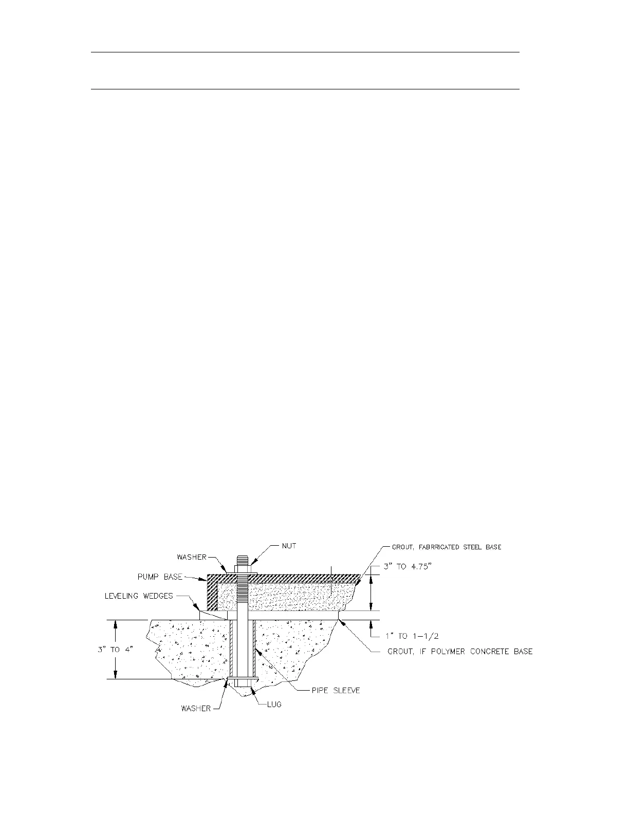
The mass weight of the sub foundation should be 3-5 times the mass weight of pump,
motor and baseplate. Dimensionally, it should be 3” to 6” longer and wider than the
polymer concrete or fabricated steel baseplate. Anchor bolts are installed in pipe sleeves.
The pipe diameter is 2.5 times larger than the anchor bolt diameter. This sleeve/bolt
assembly is embedded in the base when poured.
Anchor bolt sizes: 1”-8UNC. Length is 7.5 to 10” depending on base thickness and
overall size.