18 Section 4. Hardware Reference
Detector Array
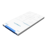
The markers in the array section provide indicate proper light field and array calibration step
positions. Additional array calibration markers are provided on the bottom panel.
Figure 4-3. Detector Array Markers
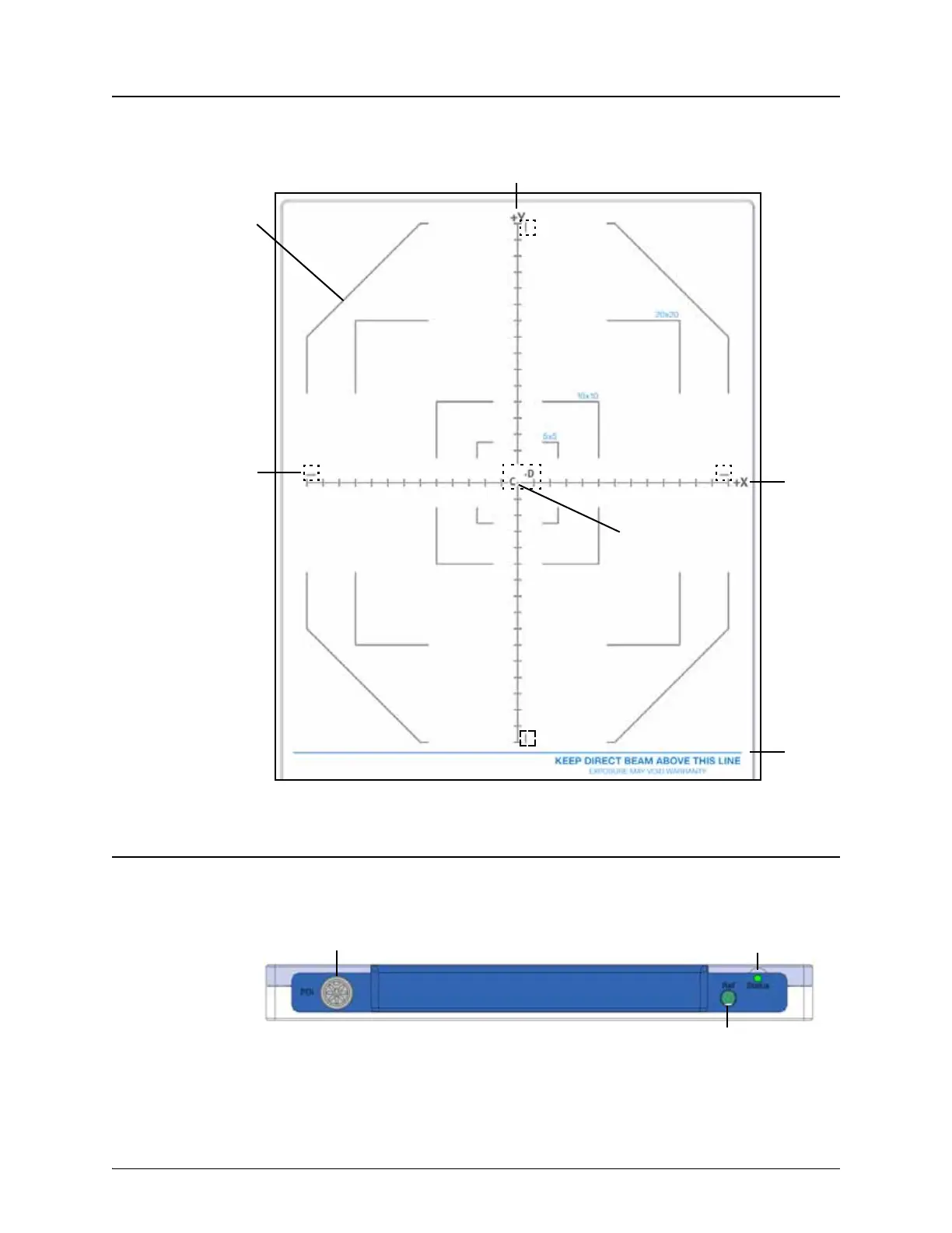
Connector Panel
The MapCHECK 3 connector panel has a power and data connector (PDI), a coaxial connector for
a reference detector (Ref), and an indicator LED (Status). The reference detector input is only
intended for MapCHECK 3 manufacturing testing.
Figure 4-4. Connector End Panel
The serial number label is typically located at the lower left of the connector panel.
Light field markers:
5 x 5 cm,
10 x 10 cm,
20 x 20 cm, and
measurement perimeter
Array calibration
step C and D markers
(dash boxes)
Y axis marker
X axis
marker
Do not
irradiate
below
this line
Center
detector
Status LED
PDI 3.0 DIN connector
Reference detector coax connector