6 Inverter Installation
E500 Series Universal Low-Power Inverter
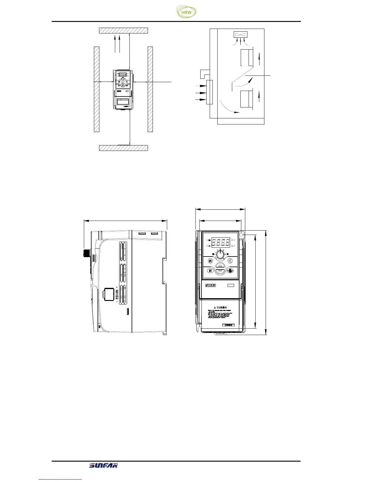
Figure 2-1-C
Figure 2-1-B Installation Spacing Distance Installation of Multiple Inverters
2.2 Installation dimension of inverters
2.2.1 Installation dimension of inverters
E500
D
H
H1
W
W1
Applicable models: E500-2S0004 (B) ~E500-2S0007 (B), shown in Figure 2-2-A
Figure 2-2-A Inverter Installation Dimension 1
导流隔板
变
频
器
变
频
器
Baffle plate
Inverter
Inverter
WARNING
1.Refer to the instruction manual before installation
3.Do not remove any cover while appl ying power
a nd a t l ea s t 10 m in . af t er d i s con ne ctin g po we r.
4.Securely ground(earth) the equipment.
2.Do not connect AC power to output terminals UVW.
and operation.
!
风扇排气
50mm以上
120mm以上
50mm以上
120mm以上
Fan exhaust
50mm