Operating Panel 19
E500 Series Universal Low-Power Inverter
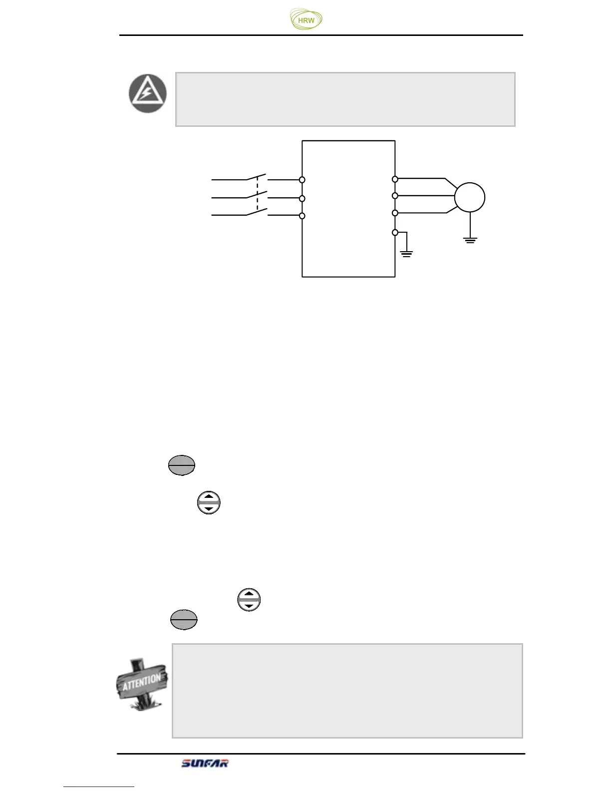
4.4.2 Simple running
Figure 4-2 Simple Running Wiring Diagram
① Connect wires as per Figure 4-2;
②
Switch on the power supply after confirming that the wires are connected
correctly, and the inverter will firstly display “P.oFF” and then “0”.
③
Confirm that the frequency setting channel is at the digit setting model
([F0.00] = 0);
④
It is required to set parameter [F0.12] and [F0.13] according to the rated
nameplate data on the inverter’s dragging motor.
⑤
Press key to start the inverter and the inverter will input 0 frequency,
displaying “0.0”.
⑥ Press Up of key to increase set frequency, and the output frequency of the
inverter will increase and the motor revolution will also increase.
⑦
Check if the motor run normally. In case of any abnormity, stop running the
motor immediately and disconnect power supply. Do not run the motor until fault
cause is found.
⑧
Press Down on the key to decrease set frequency.
⑨
Press key again to stop running and cut off the power supply.
STOP
RUN
STOP
RUN
M
电动机
U
W
V
R
S
T
三相电源
×
×
×
三相断路器
接大地
E
Earthing
Motor
Three-phase circuit breaker
Three-
It is absolutely forbidden to connect the power cord to the
output U, V, W of the frequency inverter.
The default value of the carrier frequency is fixed (1.5-10 KHz). If the
motor is completely empty-load, slight oscillation may occur sometimes
in the operation under high carrier frequency. At this time, please reduce
the setting value of the carrier frequency. (Parameter [F0.08]).