50 Function Parameter Table
E500 Series Universal Low-Power Inverter
This parameter group is used to set DC braking parameters at stop.
During the process of DC braking initial frequency ([F2.03]) at stop setting
inverter stop, when the output frequency is lower than the set parameter, the
inverter will lock output and enable DC braking function. The stop DC braking
action time is to be set by parameter [F2.05]. The stop DC braking action time is
set to 0, the stop DC braking function is ineffective.
Stop DC braking current means the percentage of inverter’s rated current.
This
parameter is used to set the allowed output level of torque current at
acceleration.
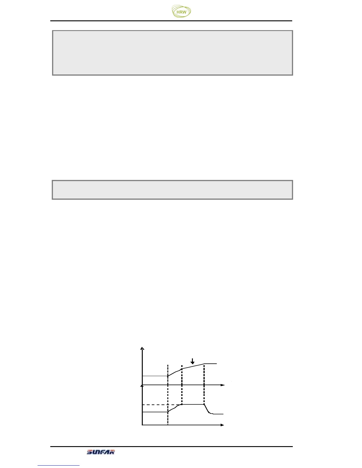
The torque limiting level during inverter acceleration is set by [F2.06]. It is set to
the percentage of inverter’s rated current. For example, if it is set to 150%, it
means the output current is 150% of the rated current at maximum.
When the inverter’s output current is higher than the level specified by these
parameters, the
acceleration and deceleration time will be prolonged
automatically so as to confine the output current within this level range. Refer to
Figure 6-13.
Therefore, if the acceleration time is required to be shorter, acceleration torque
level needs to be increased.
F2.03 DC braking initial frequency at stop Setting range: 0.0 ~ [F0.04]
F2.04 DC current at stop Setting range: 0.0 ~ 100%
F2.05 DC braking time at stop Setting range: 0 ~20.0 Sec.
F2.06 Acceleration torque level Setting range: 110 ~ 200
(%)
[F2.0 6]
频率
时间
时间
加速时 间 调整
加速力 矩
Time
Time
Frequency
Acceleration torque
Acceleration time adjustment
[F2.06]