Functional Details 63
E500 Series Universal Low-Power Inverter
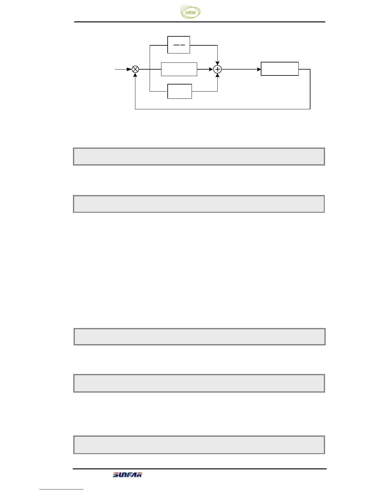
Figure 6-18 PID Function Sketch
0: PID function disabled 1: PID function enabled
It is used to select the setting channel of the PID target value.
0: Digital setting by [F5.02] 1: frequency input channel setting
PID’s set target value is a relative value. The setting 100% is corresponding to
100% of feedback system of the controlled system.
PID feedback channel is fixed as AI input, and its upper limit (100%) and lower
limit (0%) are corresponding to AI input upper limit voltage [F1.00] and AI
input lower limit voltage [F1.01].
The base value of this parameter is the system’s maximum feedback signal.
0: Feed forward function disabled 1: Feed forward function enabled
System’s response speed at start can be increasd.
????
11
Ti S
Td*S+1
+
-
???
???
P
F5.00 PID function selection Setting range: 0 ~ 1
F5.01 PID setting channel Setting range: 0 ~ 1
F5.02 PID digital setting Setting range: 0.0~100.0%
F5.04 Reserve
Contro