User Manual 10 Operation of LCD Display Panel
81
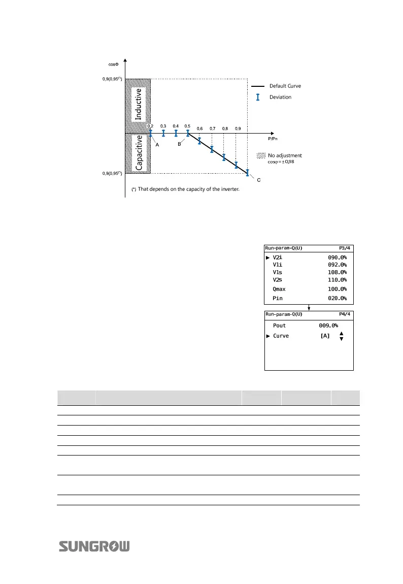
Fig. 10-6 Reactive Power Regulation Curve in “IT” Q(P) Mode
Italy “Q(U)” Mode
The reactive power ratio changes with the grid
voltage.
Select Q(U) mode and Press j
to enter into the
“Run-para-Q(U)” sub-menu.
Press j to navigate the cursor; Press h to enter into
the editing mode, then the selected parameter will be
shaded.
Press j to increase one-step value; Press h to
decrease one-step value.
Press ENTER to confirm the setting and exit from the
editing mode.
Tab. 10-10 Italy “Q(U)” Mode Parameters Explanation
Param. Explanation Default Range Step
V2i* Grid voltage at point D (in %) 90% 90%...110% 1%
V1i* Grid voltage at point C (in %) 92% 90%...110% 1%
V2s* Grid voltage at point A (in %) 108% 90%...110% 1%
V1s* Grid voltage at point B (in %) 110% 90%...110% 1%
Qmax The max. ratio of reactive power (in %) 90% 50%...100% 1%
Pin**
Enter into the Q(U) regulation mode
when the power is above Pin
20% 20%...100% 1%
Pout**
Exit from the Q(U) regulation mode
when the power is below Pout
9% 1%...20% 1%
Curve Curve type A A/B -
*V2i < V1i < V1s < V2s **Pin > Pout
 Loading...