101
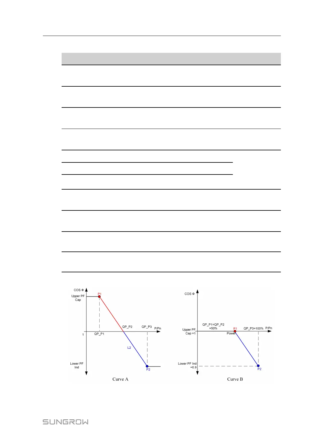
table 7-8 "Q(P)" Mode Parameters Explanation
Parameter Explanation Range
Q(P) Curve Select corresponding curve according to local
regulations
A, B, C
*
QP_P1 Output power at point P1 on the Q(P) mode curve
(in %)
0 %–100.0 %
QP_P2 Output power at point P2 on the Q(P) mode curve
(in %)
20.0 %–100.0 %
QP_P3 Output power at point P3 on the Q(P) mode curve
(in %)
20.0 %–100.0 %
QP_K1 Power factor at point P1 on the Q(P) mode curve Curve A/C: 0.800
to 1.000
Curve B: -0.600
to 0.600
QP_K2 Power factor at point P2 on the Q(P) mode curve
QP_K3 Power factor at point P3 on the Q(P) mode curve
QP_
EnterVoltage
Voltage for Q(P) function activation (in %) 100.0 %–110.0
%
QP_
ExitVoltage
Voltage for Q(P) function deactivation (in %) 90.0 %–100.0 %
QP_
ExitPower
Power for Q(P) function deactivation (in %) 1.0 %–100.0 %
QP_
EnableMode
Unconditional activation/deactivation of Q(P)
function
Yes, No
* Curve C is reserved and consistent with Curve A currently.
figure 7-20 Reactive Power Regulation Curve in Q(P) Mode
"Q(U)" Mode
User Manual 7 iSolarCloud App