31
The cable colors in figures in this manual are for reference only. Please select ca-
bles according to local cable standards.
5.2 Terminal Description
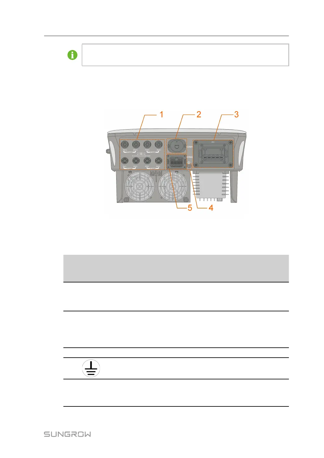
All electrical terminals are located at the bottom of the inverter.
figure 5-1 Terminals (SG20RT for example)
* The image shown here is for reference only. The actual product received may differ.
table 5-1 Terminal Description
No. Name
Description
Decisive Volt-
age
Classification
1
PV1+, PV1–, PV2+,
PV2–, PV3+, PV3–,
PV4+, PV4–
MC4 terminals for PV input.
The terminal number depends on in-
verter model.
DVC-C
2 COM1
Communication accessory port to be
connected to WiNet-S/WiNet-S2 for
countries except Brazil or to WiFi for
Brazil.
DVC-A
3 AC
AC terminal to connect to the grid.
DVC-C
4
External grounding terminal. Not applicable
5 COM2
Communication connection for DI/
DRM, DO, Logger and smart energy
meter.
DVC-A
The pin definition of COM2 terminal is shown in the following label.
User Manual 5 Electrical Connection