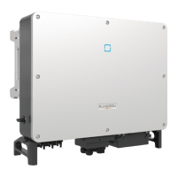
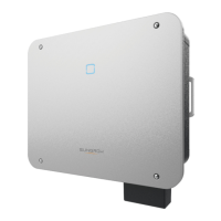
Do you have a question about the Sungrow SG20KTL and is the answer not in the manual?
Manual provides guidelines and additional info for inverter operation.
Manual is for technical personnel and owners; details usage instructions.
Indicates high risk of death or serious injury if not avoided.
Indicates medium risk of death or serious injury if not avoided.
Indicates low risk of minor or moderate injury if not avoided.
Indicates potential equipment or property damage if not avoided.
Symbols indicating safety precautions and warnings on the inverter body.
Symbols related to operational safety, qualified personnel, and load handling.
General safety instructions for installation, commissioning, operation, and maintenance.
Defines qualifications and tasks for personnel performing installation and service.
CAUTION about handling device and NOTICE about shipping damage.
DANGER if not electrically connected, CAUTION on ventilation.
NOTICE on standards compliance and grid connection permission.
DANGER about lethal voltage from PV arrays and WARNING on cable integrity.
DANGER on disconnecting under load, CAUTION on hot surfaces.
DANGER on incorrect service, CAUTION on keeping people away, NOTICE on immediate repair.
Servicing requires proper tools, test equipment, and up-to-date manual.
NOTICE on using approved parts and avoiding modifications.
NOTICE on handling sensitive circuit boards and ESD precautions.
NOTICE on country settings by service personnel only; WARNING on labels.
Describes the inverter's purpose as a grid-connected PV system component.
WARNING: Inverter CANNOT connect to PV modules with grounded terminals.
Identifies and describes the main components of the inverter unit.
Provides physical dimensions and net weight for different inverter models.
Describes the LCD display panel, its indicators, and buttons.
Explains the meaning of the "RUN" and "FAULT" LED indicators.
Explains the purpose and operation of the DC switch for safety.
Explains the transformer-less, grid-connected inverter's main circuit diagram and operation.
Details conversion, data storage, parameters, communication, and protection functions.
Explains derating triggers and PV overload derating with a table.
Describes grid under-voltage and over-temperature derating with diagrams.
Mentions user adjustment of output power via LCD panel.
Visual flowchart detailing the step-by-step installation process for installers.
Detailed description of each installation step with corresponding chapter references.
Guides users on how to unpack and inspect the inverter for damage.
Explains how to identify the inverter using its nameplate and icons.
Lists all items included in the inverter package with descriptions.
Provides recommendations for storing the inverter under various conditions.
Discusses criteria for choosing a suitable and safe location for inverter mounting.
Details correct mounting orientation, temperature, and humidity requirements.
Specifies locations to avoid, such as direct sunlight, closed cabinets, and reachable by children.
Provides instructions and safety tips for safely moving the inverter.
Shows dimensions of the mounting backplate.
Step-by-step guide for attaching the backplate to a concrete wall.
Instructions for lifting and securing the inverter to the mounted backplate.
Step-by-step guide for attaching the backplate to a metal frame.
Details on fastening the backplate to a metal frame using bolts and nuts.
Instructions for attaching the inverter to the backplate on a metal frame.
Identifies and describes the various terminals on the inverter.
Shows a general diagram for connecting the inverter to the PV system and grid.
Details the electrical connection diagram, including PV arrays, logger, PC, breaker, and grid.
Specifies the recommended AC circuit breaker ratings for different inverter models.
Discusses RCD requirements and parallel connection guidelines.
Details AC cable requirements, including impedance, length, and conductor size.
Step-by-step guide for connecting SG10KTL to the AC grid.
Step-by-step guide for connecting SG20KTL to the AC grid.
Details latching, fastening, and grounding the AC connector and cables.
DANGER of lethal voltage and WARNING on impedance checks before connecting PV arrays.
Introduces Independent and Parallel PV input modes.
Explains independent mode operation and requirements for PV strings.
Explains parallel mode operation and requirements for PV strings.
Details DC cable cross-section, diameters, voltage, and current ratings.
Step-by-step guide for assembling DC cable ends with crimp contacts.
DANGER for live DC cables; procedures for connecting PV arrays in independent mode.
Emphasizes checking PV string polarity and voltage limits before connecting.
Steps for connecting PV strings in parallel mode, including shorting input areas.
WARNING against grounding DC poles; overview of grounding requirements for the system.
Illustrates grounding for PV power systems with multiple inverters.
Describes the availability and use of second PE terminals for connection.
Introduces RS485 interface for transferring operational data to PC or logger.
Lists requirements for RS485 cables and CAUTION on lighting protection.
Explains communication system for single and multiple inverters.
Details connecting multiple inverters in a daisy chain for communication.
Steps for assembling RJ45 plugs and connecting RS485 cables to devices.
Lists essential checks to be performed before starting the inverter commissioning.
Step-by-step guide to start up and commission the inverter for the first time.
Guides through setting language, time, and country code for the inverter.
Details setting grid codes and configuring protective parameters.
Steps to set PV configuration mode and confirm all settings.
Procedures for safely disconnecting the inverter from AC and DC power sources.
Refers to previous chapters for dismantling and highlights responsibility for disposal.
Guides on troubleshooting issues indicated by LED indicators.
Provides a table for diagnosing and resolving faults displayed on the LCD screen.
Details troubleshooting steps for specific fault codes related to grid voltage and frequency.
Guides on resolving faults related to islanding, DC current, failure currents, and grid abnormalities.
Details troubleshooting for PV input overcurrent, configuration issues, and temperature problems.
Covers faults related to boost circuits, configuration mismatch, sampling, and protection circuits.
Outlines routine maintenance tasks and their recommended periods.
Step-by-step instructions for cleaning the inverter's fans safely.
Instructions for replacing the inverter fans, emphasizing technician involvement.
Guidance on cleaning air inlets and outlets for maintaining ventilation.
Provides contact information and required details for technical assistance.
Explains the functions of the ESC and ENTER buttons on the inverter's LCD panel.
Illustrates the hierarchical structure of the inverter's menu system.
Describes the information presented on the inverter's main LCD screen.
Explains different inverter states like Run, Standby, Stop, and Fault.
Steps for adjusting the contrast of the inverter's LCD display for better readability.
Explains how to access and interpret detailed running information on the LCD.
Guides on how to view historical running data pages.
Explains how to access and view the inverter's fault records.
Step-by-step instructions for starting and stopping the inverter via the LCD menu.
Explains the password protection for parameter settings and how to enter it.
Details how to configure the display language for the inverter.
Explains the importance and procedure for setting the correct time.
Guides on adjusting energy values if they differ from external metering.
Explains how to reset parameters to default values and the implications.
Describes how to view the inverter's firmware version details.
Details how to access and set running parameters like standby time and P-W limits.
Table detailing parameters like Standby time, Recover time, P-W limits, and PF.
Explains Pf, Qt, Off, Q(P), and Q(U) modes for reactive power regulation.
Details Italy-specific Q(P) mode parameters and their settings.
Details Italy-specific Q(U) mode parameters and their settings.
Instructions for saving or restoring P/Q-set values upon power down.
Explains the purpose of protective parameters and country code selection.
Guides on selecting grid codes and enabling/disabling LVRT function.
Details the single-stage protective parameter settings.
Details the multi-stage protective parameter settings.
Explains Stage I protective parameters for Italy.
Explains Stage II protective parameters for Italy.
Guides on setting communication parameters like address.
Details how to set the PV configuration mode (Independent/Parallel).
Explains Italy-specific derating based on grid frequency.
Details Italy-specific Q(P) mode reactive power regulation.
Details Italy-specific Q(U) mode reactive power regulation.
Provides recovery values for grid protection parameters in Italy.
Explains Stage I protective parameters for Italy.
Explains Stage II protective parameters for Italy.
Provides detailed technical specifications for the inverter models.
Lists AC output power, voltage, frequency, and current specifications.
Details protection features, efficiency, isolation, and environmental ratings.
Specifies communication interfaces and recommended conductor sizes for terminals.
Details conditions under which Sungrow rejects liability for damages.
Provides information about the manufacturer and its product range.
Lists contact details for inquiries and assistance.
| Model | SG20KTL |
|---|---|
| Type | String Inverter |
| Rated Output Power | 20 kW |
| Max. DC Input Power | 30 kW |
| Max. DC Input Voltage | 1100 V |
| Start Voltage | 200 V |
| Number of MPPTs | 2 |
| Max DC Input Current per MPPT | 26 A |
| Max. Input Current per MPPT | 26 A |
| Rated AC Power | 20 kW |
| Rated AC Voltage | 400 V |
| AC Voltage Range | 310 V - 480 V |
| Rated Grid Voltage | 400 V |
| Rated Grid Frequency | 50 Hz / 60 Hz |
| Total Harmonic Distortion | < 3% |
| Power Factor at Rated Power | 1 |
| Adjustable Power Factor Range | 0.8 leading - 0.8 lagging |
| Max. Efficiency | 98.6% |
| European Efficiency | 98.4% |
| Efficiency | 98.6% |
| DC Switch | Yes |
| Protection Class | IP65 |
| Cooling Concept | Natural Cooling |
| Max. DC Power | 22000 W |
| Max. AC Power | 22 kW |
| Grid Frequency | 50/60 Hz |
| Operating Temperature Range | -25 °C ~ +60 °C |
| Input Voltage Range | 200 V - 1000 V |


