32
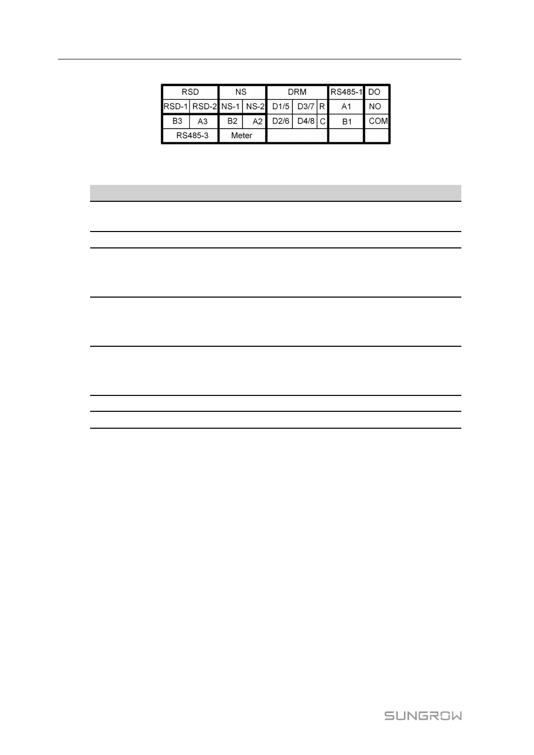
figure 5-2 Label of COM2 Terminal
table 5-2 Label Description of COM2 Terminal
Label
Description
RSD
RSD-1,
RSD-2
For inverter emergency stop
NS
NS-1, NS-2
For inverter emergency stop
DRM
D1/5, D2/6,
D3/7, D4/8,
R, C
For external Demand Response Enabling Device ("AU"/
"NZ")
For Ripple Control
RS485-1
A1, B1
For inverter daisy chain
(Cannot be used simultaneously with COM1 port for WiNet-
S/WiNet-S2)
DO
NO, COM
External alarm interface, e.g. light indicator and/or buzzer
The external DC voltage should not be higher than 30 V and
the current not higher than 1 A.
RS485-3
A3, B3
Reserved
Meter
A2, B2
Smart energy meter interface
*
* In case communication failure occurs to the meter as a result of adopting a longer commu-
nication cable, you may connect a 120Ω resistor in parallel across ports A and B of the meter
to resolve this issue.
5.3 Electrical Connection Overview
The SG3.0-20RT electrical connection should be realized as follows:
5 Electrical Connection User Manual