39
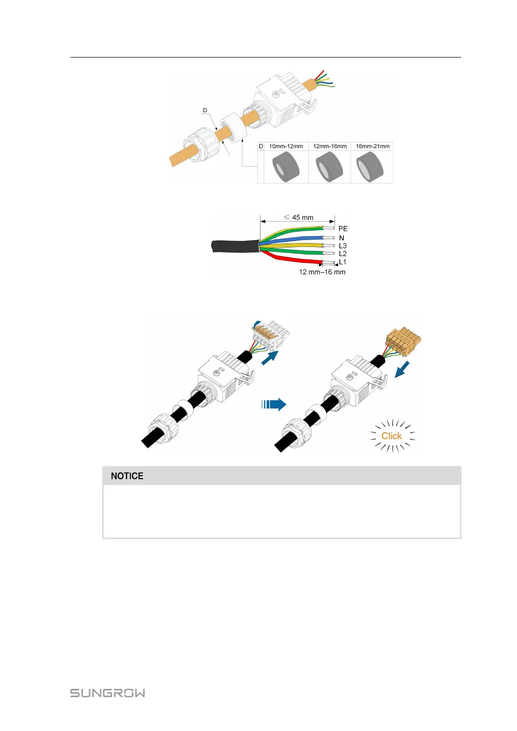
step 4 Remove 45 mm of the cable jacket and 12 mm–16 mm of the wire insulation.
step 5 Open the clamp on the spring-loaded terminal and insert the wires into the corresponding
holes. Close the clamp and push the terminal into the housing until there is an audible click.
Observe the terminal assignment. Do not connect any phase line to the "PE" termi-
nal or PE wire to "N" terminal. Otherwise, unrecoverable damage to the inverter
may follow.
step 6 Ensure that the wires are securely in place by slightly pulling them. Tighten the swivel nut to
the housing.
User Manual 5 Electrical Connection