50
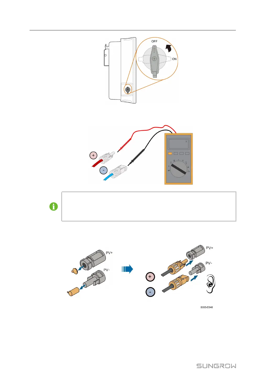
step 2 Check the cable connection of the PV string for polarity correctness and ensure that the
open circuit voltage in any case does not exceed the inverter input limit of 1,100 V.
The multimeter must have a DC voltage range of at least 1100 V. If the voltage is a
negative value, the DC input polarity is incorrect. Please correct the DC input po-
larity. If the voltage is greater than 1100V, too many PV modules are configured to
the same string. Please remove some PV modules.
step 3 Connect the PV connectors to corresponding terminals until there is an audible click. Seal
the unused PV terminals with the terminal caps.
step 4 Connect the PV+ and PV- of the optimizer to the positive and negative terminals in the junc-
tion box of the PV module respectively.
5 Electrical Connection User Manual