User Manual 2 Product Description
19
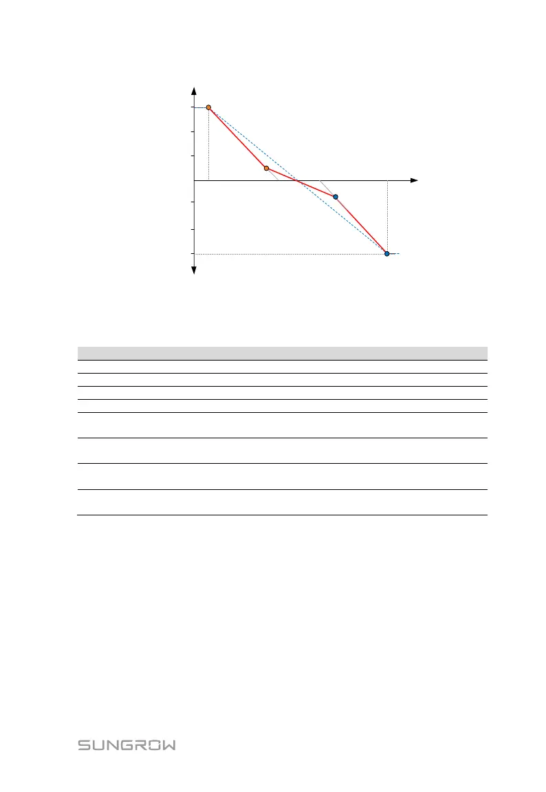
Max. leading
Q/Sn
Max. lagging
Q/Sn
Grid voltage, V
Q/Sn
P2
P3
P4
0%
P1
V1 Ref. V2 Ref.
V3 Ref. V4 Ref.
Fig. 2-13 Reactive Power Control Curve in Q(U) Curve (“NL”, “EU”, “PL”)
Q(U) curve for the country Italy (“IT”)
Tab. 2-16 Italy “Q(U)” Mode Parameters Explanation
Grid voltage at point A (in %)
Grid voltage at point B (in %)
Grid voltage at point C (in %)
Grid voltage at point D (in %)
The ratio of the base reactive power
(in %)
Enter into the Q(U) regulation mode
when the power is above Pin
Exit from the Q(U) regulation mode
when the power is below Pout
The max. ratio of reactive power
(in %)
*V2i < V1i < V1s < V2s **Pin > Pout

 Loading...