7 LCD Operation User Manual
58
7.5.2 Setting Protective Parameters
Protective parameters are designed for the thresholds that can trigger the
protective function of the inverter. The thresholds are compliant with the
requirements of local safety standards and the utility grid.
If the protection function is triggered, the inverter will automatically disconnect
from the grid with the ”Error xxx” state displayed on the LCD main screen. After
the grid voltage or frequency recovers to the specified range, the inverter will
start running normally and can reconnect to the grid.
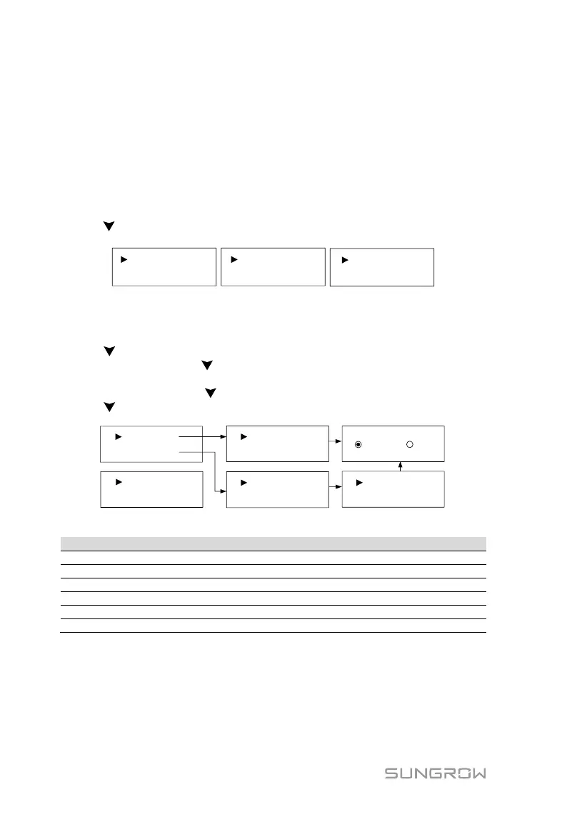
Touch to select the item and touch ENT to enter the setting interface.
Volt-watt
Single/Mul Prot.
Prot. Recover
Grid Prot. Adj.10 Min Over Vtg En.
Esc
* The Volt-watt item is not supported for Europe.
Single/Multiple Protection
Touch to select the item and touch ENT for modification.
When modifying, touch to change the value and touch ENT to move the
cursor.
Scroll pages by touching .
Touch to select “Enter” and touch ENT to confirm settings.
2-Vmax: 287.5V
2-Vmin: 103.5V
1-Vmax: 287.5V
1-Vmin: 184.0V
Multi. stage
Single stage
Vmin: 184.0V
Vmax: 287.5V
Enter Esc
Esc
Tab. 7-3 Protective Parameters and the Range
Grid over-voltage 2 (V>>)
Grid under-voltage 1 (V<)
Grid under–voltage 2 (V<<)
The values listed in the following table are for your reference only. Please follow
the requirements of local grid standard. Refer to Tab. 7-6 for the descriptions of
the country codes.

 Loading...