2 Product Description User Manual
22
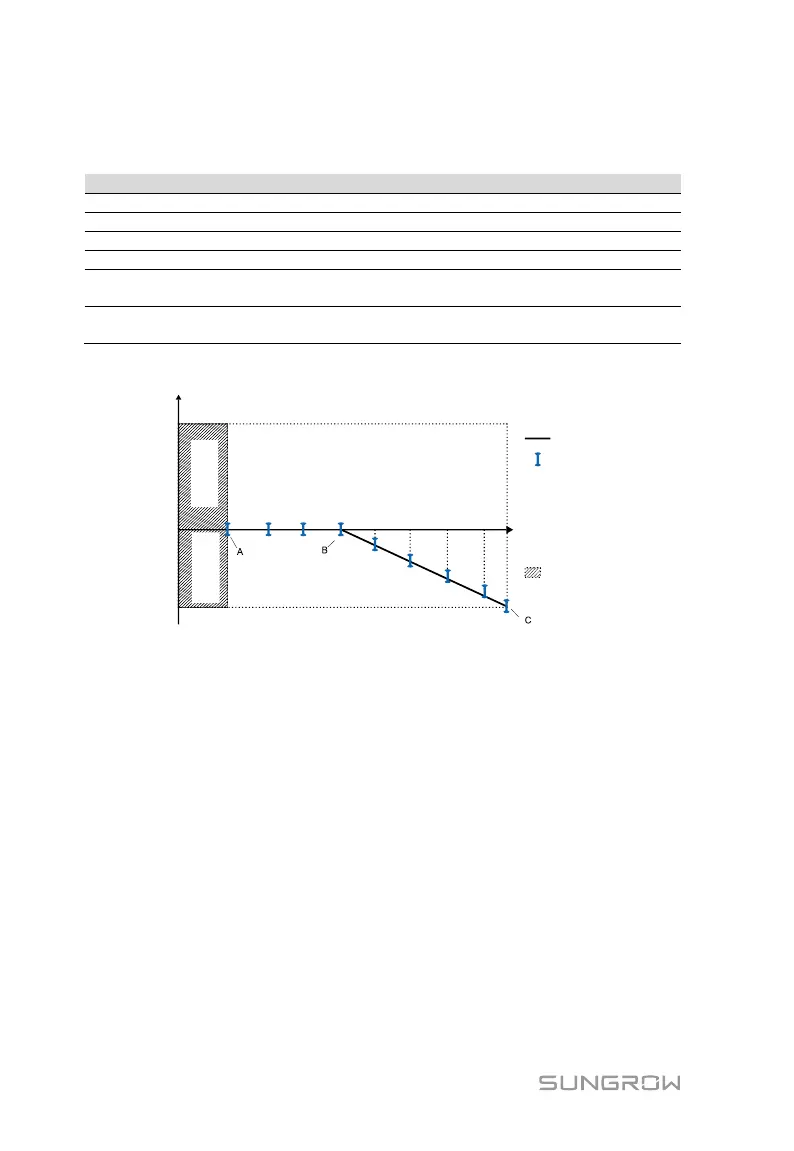
Q(P) curve for the country Italy (“IT”)
Tab. 2-20 Italy “Q(P)” Mode Parameters Explanation
Fig. 2-17 Reactive Power Regulation Curve in “IT” Q(P) Mode
2.3.6 SPI and Auto Test (Italy only)
The auto test system will check the maximum/minimum frequency and voltage
provided in the interface protection system (SPI). For each frequency and
voltage protection function, the tripping threshold varies linearly upward or
downward with a slope of ≤ 0.05 Hz/s or ≤ 0.05 V/s respectively for the
frequency and voltage protection. For details, see “7.11.1 Auto Test”.
The SPI local control via the LCD setting is capable to change the frequency
protection thresholds. For details, see “7.11.2 SPI Local Control”.
The frequency protection thresholds can also be set via RS485 by an external
device. Through the external signal/command:
Low (state value 0) in case of really operating communication
High (state value 1) in case of external commands sent by the external
device

 Loading...