User Manual 5 Electrical Connection
49
Tab. 5-2 Pin Definitions of the RJ45 Plug
Pin 1 and pin 2 are configured to supply power for
communication modules. Never connect or use these two pins
when preparing the RS485 communication cable. Otherwise,
damage can be caused to inverters or other devices connected
through the communication cable.
2. Take out the meter communication connector from inverter’s
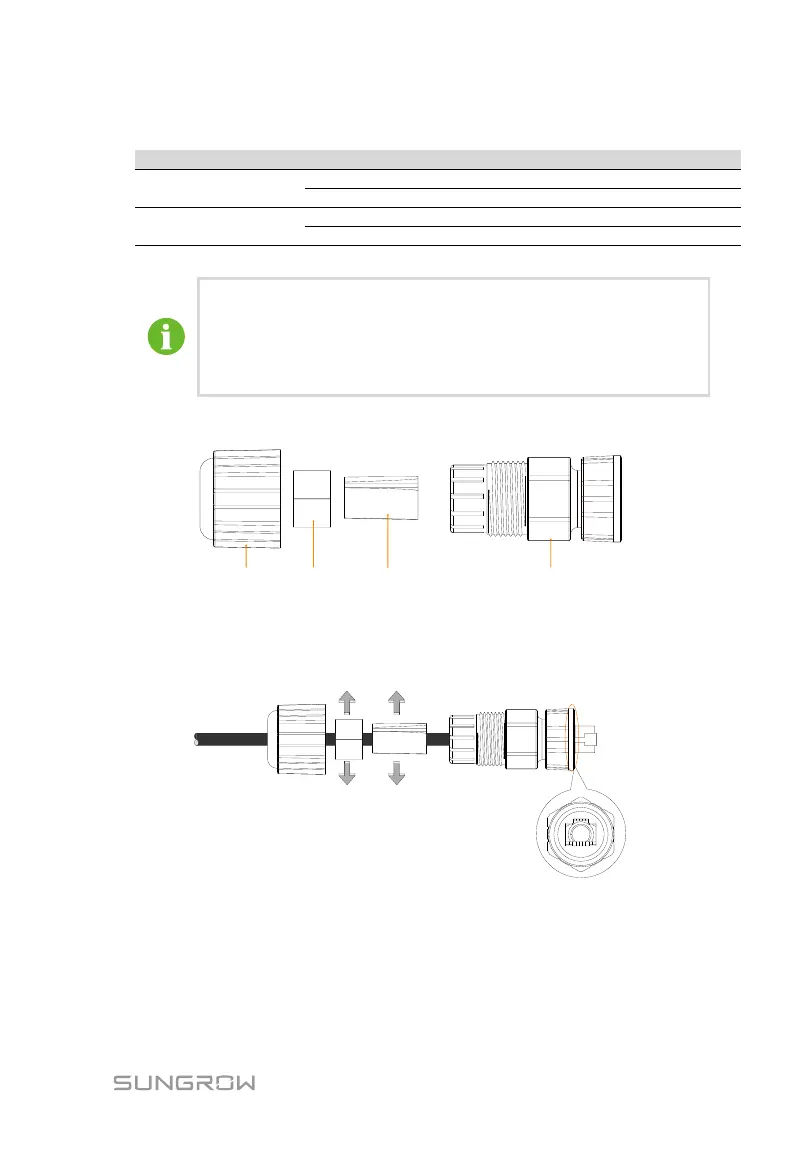
packaging. The components are shown as follows.
A
A
A
A
A
A
A
A
A
A
A
A
A
A
A
A
A
A
A
A
A
A
A
A
A
A
A
A
A
A
A
A
A
A
A
A
A
A
A
A
A
A
A
A
A
A
A
A
A
A
A
A
A
A
A
A
A
A
A
A
A
A
A
A
A
A
A
A
A
A
A
A
A
A
A
A
A
A
A
A
A
A
A
A
A
A
A
A
A
A
A
A
A
A
A
A
A
A
A
A
A
A
Sealing nut Seal Support Housing and screw nut
3. Lead the communication cable through the components according to
the following sequence. Align the RJ45 plug and the slot on the
housing. The cable should be fully inserted until the RJ45 plug is
positioned to the place.
A
A
A
A
A
A
A
A
A
A
A
A
A
A
A
A
A
A
A
A
A
A
A
A
A
A
A
A
A
A
A
A
A
A
A
A
A
A
A
A
A
A
A
A
A
A
A
A
A
A
A
A
A
A
A
A
A
A
A
A
A
A
A
A
A
A
A
A
A
A
A
A
A
A
A
A
A
A
A
A
A
A
A
A
A
A
A
A
A
A
A
A
A
A
A
A
A
A
A
A
A
A
4. Push the support and the seal into the housing. Then tighten the
sealing nut to the housing.
 Loading...