56
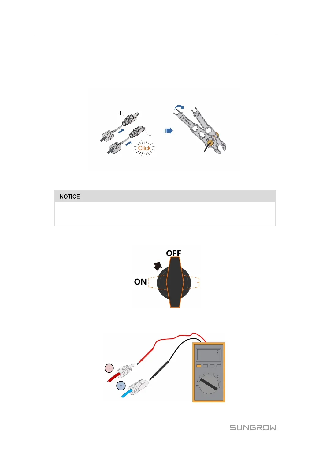
1: Positive crimp contact 2: Negative crimp contact
step 3 Lead the cable through cable gland, and insert the crimp contact into the insulator until it
snaps into place. Gently pull the cable backward to ensure firm connection. Tighten the ca-
ble gland and the insulator (torque 2.5 N.m to 3 N.m).
step 4 Check for polarity correctness.
If the PV polarity is reversed, the inverter will be in a fault or alarm state and will
not operate normally.
step 5 Rotate the DC switch to “OFF” position.
step 6 Check the cable connection of the PV string for polarity correctness and ensure that the
open circuit voltage in any case does not exceed the inverter input limit of 1,000V.
step 7 Connect the PV connectors to corresponding terminals until there is an audible click.
6 Electrical Connection User Manual
 Loading...