61
step 3 Refer to the guide delivered with the module for the set-up.
- - End
6.8.1.2 Ethernet Communication
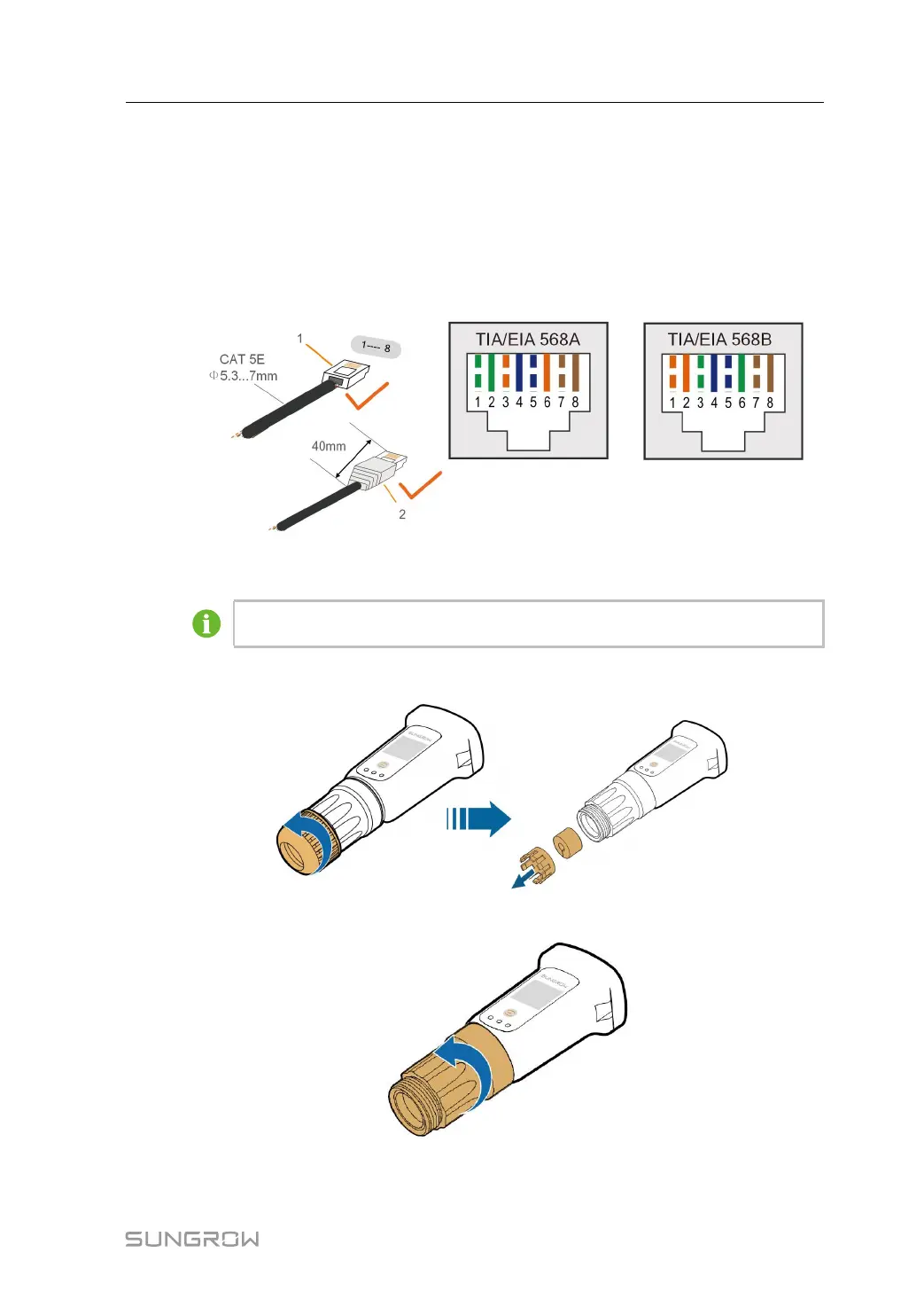
step 1 (Optional) Strip the insulation layer of the communication cable with an Ethernet wire strip-
per, and lead the corresponding signal cables out. Insert the stripped communication cable
into the RJ45 plug in the correct order, and crimp it with a crimper.
1: RJ45 plug 2: Protective cap
Skip this step if a standard network cable with RJ45 plug is prepared.
step 2 Unscrew the swivel nut from the communication module and take out the inner sealing ring.
step 3 Unscrew the housing from the communication module.
step 4 Thread the network cable through the swivel nut and gasket. Afterwards, route the cable into
the opening of the sealing. Finally, insert the cable through the housing.
User Manual 6 Electrical Connection
 Loading...