Operation manual of solar controller SR1568
Page 7 of 87
Power supply : 100…240V ~(50…60Hz)
Rated impulse voltage::2.5KV
Data interface : TF (Micro SD)
485 current supply:60mA
Housing:Plastic ABS
Mounting:Wall mounting
Indication / Display: System-Monitoring-Display, for visualization of the systems, TFT
colorful display, and background illumination
Operation: 5 push buttons at the front cover
Protection type: IP41
Protection class: I
Ambient temperature: 0 ... 40 °C
Degree of pollution: 2
Dimensions: 208*158*43mm
Note: TF (Micro SD) isn’t included in the delivery list
3. Installation
Note: The unit must only be located in the dry interior rooms. Please separate
routing of sensor wires and mains wires. Make sure the controller as well as the system is
not exposed to strong electromagnetic fields.
3.1 Mounting controller
Follow the below steps to mount the controller on the wall.
Unscrew the crosshead screw from the cover and
remove it along with the cover from the housing.
Mark the upper fastening point on the wall. Drill and
fasten the enclosed wall plug and screw leaving the
head protruding.
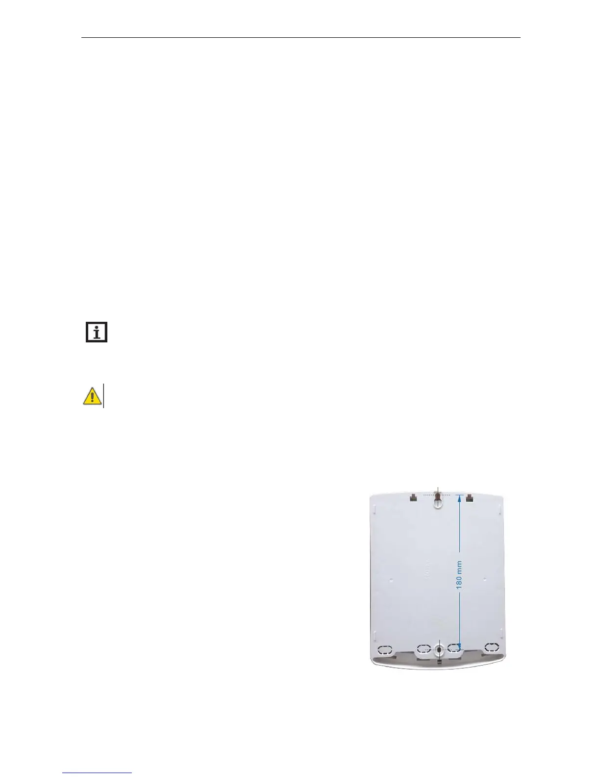
Hang the housing from the upper fastening point and
mark the lower fastening points (centers 180 mm).
Drill and insert lower wall plugs.
Fasten the housing to the wall with the lower fastening
screw and tighten.
Carry out the electrical wiring in accordance with the terminal allocation