This document describes the Atrix basic-5/10/15/20 Series Residential Energy Storage Systems, a product from SUNWODA ENERGY. This user manual provides comprehensive information on the device's function, technical specifications, usage, and maintenance.
Function Description
The Atrix basic series is a lithium battery energy storage system designed for residential use. It is based on the chemical composition of Lithium Iron Phosphate (LFP) and adopts a modular parallel design, allowing for flexible expansion of energy storage capacity. The system includes a data display box (optional) and multiple battery modules, supporting up to 4 battery modules in parallel. The battery energy storage system can be used with an inverter and communicates via CAN. The system supports up to 2 single systems connected in parallel, which can be expanded to 40kWh. The battery management system provides data collection, status monitoring, and control to ensure safe and reliable operation. The system adopts IP20 protection design for indoor use.
The system's primary function is to store electrical energy for later use, providing a reliable power source for residential applications. It is designed to integrate with an inverter to manage the flow of energy between the grid, solar panels (if applicable), and the battery system.
Important Technical Specifications
The Atrix basic series offers different models with varying energy capacities:
- Atrix basic-5: 5kWh
- Atrix basic-10: 10kWh
- Atrix basic-15: 15kWh
- Atrix basic-20: 20kWh
General Specifications:
- Module model: B051100P01
- Rated voltage: 51.2V
- Rated energy: 5kWh (per module)
- Rated charging and discharging current for system:
- Atrix basic-5: 50A
- Atrix basic-10: 100A
- Atrix basic-15: 150A
- Atrix basic-20: 200A
- Max. charging and discharging current for system:
- Atrix basic-5: 100A
- Atrix basic-10: 180A
- Atrix basic-15: 200A
- Atrix basic-20: 200A
- Working voltage range: 44.8V~55.2V
- Communication: CAN
- Protection function: Charging over voltage, discharging under voltage, over current, over temperature, short circuit protection.
- Cycle life: 6000 cycles (25°C, 0.5C, 90%DOD, EOL 70%)
- Scalability: Maximum 4 module parallel for one cluster; Maximum 2 clusters parallel with combiner bus-bar.
- Enclosure protection rating: IP20
- Working ambient temperature: Charging: (0,50]°C, Discharging: (-20,50]°C
- Working ambient humidity: 10%~95%RH
- Altitude: <4000m, Derating above 2000m
- Certificate: IEC62619, CE, UN38.3
Physical Dimensions (per module):
- Size (WDH): 443mm * 410mm * 135mm
- Weight: 45kg (99.2lbs)
Specific Dimensions for different configurations:
- Atrix basic-5: Height 188mm
- Atrix basic-10: Height 359mm
- Atrix basic-15: Height 530mm
- Atrix basic-20: Height 701mm
Data Display Box (Optional):
- Function: Display control of LCD screen or segment code screen, communication between battery and PCS, remote operation, parameter set, software update, compatible with multi-series of rack type product, optional based on requirement of customer and system.
- Dimension (WDH): 250mm * 200mm * 35mm
Usage Features
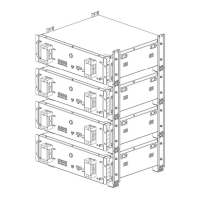
Installation:
The installation process involves several steps:
- Feet racket installation: Install the 4PCS feet and rackets.
- Easy racket installation: Install simple rackets on both sides of the battery module.
- Battery module installation: Lay the battery module with simple racket on a horizontal floor. Install other battery modules with simple racket one on one, fixing the structure with M5*10 screws after stacking. A maximum of four battery modules can be stacked.
- Data display box installation (Optional): Place the rain cover and data display box on the top battery pack.
Electrical Connection:
- Grounding: Introduce the product ground point to the nearby ground point.
- Connector installation: Connect the power cable by crimping the terminal wire, bending the cable, and locking the upper terminal hole. Cover the terminal protection cover after connection.
- Single module connection: Connect the battery module to the PCS (Power Conversion System) with specified wires for grounding, negative, positive, and communication (CAN). Terminal resistance is 120Ω.
- Parallel connection: For multiple modules, connect them in parallel to the PCS. The wiring specifications for parallel connections are provided, including power cables and communication cables. The standard wiring of the battery is 25mm², and for inverters > 5kW, 50mm² or larger specification wire harness is recommended.
- Two clusters of parallel connection: For larger systems, two clusters can be connected in parallel with a combiner bus-bar.
System Commissioning:
- System power on: Switch on the inverter (if it has a switch button). Press the POWER button for more than 3 seconds; the system will start up, and the output voltage, screen, and POWER button will light up.
- System power off: Switch off the inverter (if it has a switch button). Press the POWER button for more than 3 seconds; the system will close, the screen and POWER button will go out.
- System configuration (PowerLite APP):
- Download and install the PowerLite APP.
- Network configuration: Turn on Wi-Fi and Bluetooth on your phone. Register an account and enter verification code.
- Add site/device: Enter the account, password, and verification code. Click "Login," then "Add site." After recommending a power station, add equipment, select the SN code on the Data module, and click "Assigned Plant" to bind the battery equipment to the established power station.
- Select inverter manufacturer: Click to enter the corresponding site, click the Bluetooth SN code of the battery device to enter the battery interface, and view the device data. Click "Setting" to enter the inverter manufacturer interface for selecting the battery system configuration. After the inverter manufacturer is successfully set, the system configuration is completed.
Maintenance Features
Routine Maintenance:
- Maintenance every 6 months: From the date of manufacturer shipment, the battery shall be maintained every 6 months. Action must be taken in case SOC reaches 0% according to the ambient temperature table:
- (45, 50] °C: Must be recharged within 7 days
- (35, 45] °C: 15 days
- ≤35°C: 30 days
- Disconnect the battery if not being used: The BMS consumes power even when the battery is not being used. Disconnect the battery output to prevent the battery from becoming empty. For store-away, make sure the SOC is between 45% and 55% before disconnect.
- Check the battery system regularly: Contact support if any anomaly is detected.
Fault Checklist:
The manual provides a comprehensive fault checklist with causes and solutions for various issues, including:
- POWER button no response: Damaged POWER button, damaged cable, or poor contact, battery SOC is low, low ambient temperature. Solutions include repairing or replacing the control module, contacting the supplier, keeping the product charged, and ensuring the energy storage system is fully charged.
- Short discharge time: Product overload, batteries age and capacity decrease, internal failure. Solutions include checking load and removing non-essential loads, replacing the battery, and contacting the supplier.
- Unable to charge and discharge: Battery is discharged to SOC protection value, it needs to be charged for a period of time before it is allowed to discharge, battery over temperature. Solution is to set the SOC value by the restart.
- After the system is powered on, the LED cannot be lit: LED failure. Solution is to repair or replace the control module.
- The LED cannot wake up during system operation: If the LED is off, the POWER button is faulty or the button wiring is loose. If the LED still does not light up after resetting, the LED is faulty. Communication disconnection. Solutions include contacting the supplier, repairing or replacing the control module.
- Abnormal battery communication: The heater works abnormally. Heating circuit failure. Solutions include checking battery stack reliability, logging into PowerLite APP to view fault information, and contacting the supplier.
- Abnormal Bluetooth connection: The inverter is powered on for the first time through the battery, and the battery reports short circuit protection. Inverter won't start. The parallel capacitor value of the input terminal on the battery side of the inverter is large. The battery voltage is too low or the SOC is lower than the shutdown protection value. Solutions include checking if the paired Bluetooth is consistent with the installed product, ensuring battery protection can be automatically restored, and charging the battery after starting the inverter from the grid.
Warehouse Storage Guidelines:
- Packaging: Lithium-ion batteries are recognized as dangerous goods. The packaging requirements for battery products are as follows:
- The packaging manufacturer must be qualified for dangerous goods and have a record in the local Commodity Inspection Bureau.
- The packaging manufacturer must complete the packaging, and the supplier needs to apply to the Commodity Inspection Bureau for a "Dangerous Package Product Use Inspection Sheet" and "Dangerous package product performance inspection sheet."
- All battery packs should be packaged with product instruction manuals. The packaged product should be placed in a dry, dust-proof, and moisture-proof packing box.
- The product name, model, quantity, gross weight, manufacturer, and ex-factory date should be marked on the outside of the packing box.
- The necessary signs such as "upward" and "fear of fire" shall meet the requirements of GB/T 191.
- The packing method is: packing in a carton with molded foam buffer material in the carton; accessories packaging: single accessories are first fastened with cardboard or plastic film or braided straps, neatly placed in the carton, and filled with regular fillers (foam pads, cardboard, etc.) to prevent the accessories from shifting in the box. The following documents should be included with the product when leaving the factory: product certificate, product use (installation) manual, product packing list, and factory inspection report.
- Clean battery: Regular cleaning of the battery system is recommended. If the case is dirty, use a soft dry brush or dust collector to remove the dust. Cleaning liquid materials include solvents, abrasives, etc. Corrosive liquids should not be used to clean the housing.
- Storage conditions: The battery pack is stored in a clean, dry, and ventilated room with an ambient temperature of 25°C±5°C and a relative humidity of not more than 75%. The battery pack has a state of charge of 45% to 55%. Avoid contact with corrosive substances and keep away from fire and heat sources.
Disposal of Used Batteries:
Comply with applicable local regulations for the disposal of electronic waste and used batteries.
- Do not mix with your household waste.
- Do not expose the battery to high temperatures or direct sunlight.
- Do not expose batteries to high humidity or corrosive environments.
- Contact the supplier or original manufacturer for disposal options.