7
Battery module diagram
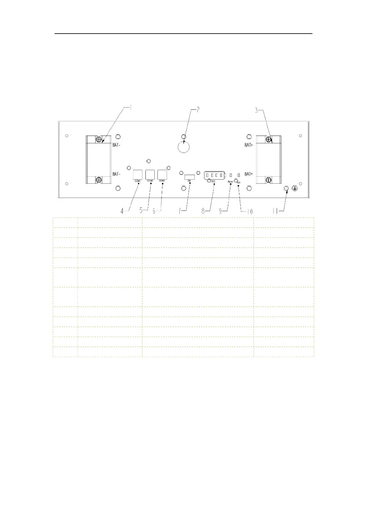
Product Front Panel Definition:
NO Item Function Note
1 .BAT- Battery output negative interface
2 POWER Battery module switch button
3 BAT+ Battery output positive interface
4 COM1 Communication interface with PCS CAN
5 COM2
Automatic addressing and internal CAN
communication interface
6 COM3
Automatic addressing and internal CAN
communication interface
7 SW One-key open interface
8 SOC Battery module SOC indicator LED light
9 Alarm Battery module fault LED light
10 Run Battery module running LED light
11 PE Battery module ground hole
2 Installation Guide
2.1 Installation site requirements
2.1.1 Environmental requirements
a. Ambient temperature: -10℃~+50℃ (recommended: 10℃~35℃ or 50℉~95℉).
b. Ambient humidity: 10-95%.
c. Altitude <= 4000 meters.
d. For indoor installation
• Avoid direct sunlight