Installation
900004-00, 01/2015
Innovative Hearth Products
Superior™ DRT2000 and DRC2000 Direct-Vent Gas Fireplaces
13
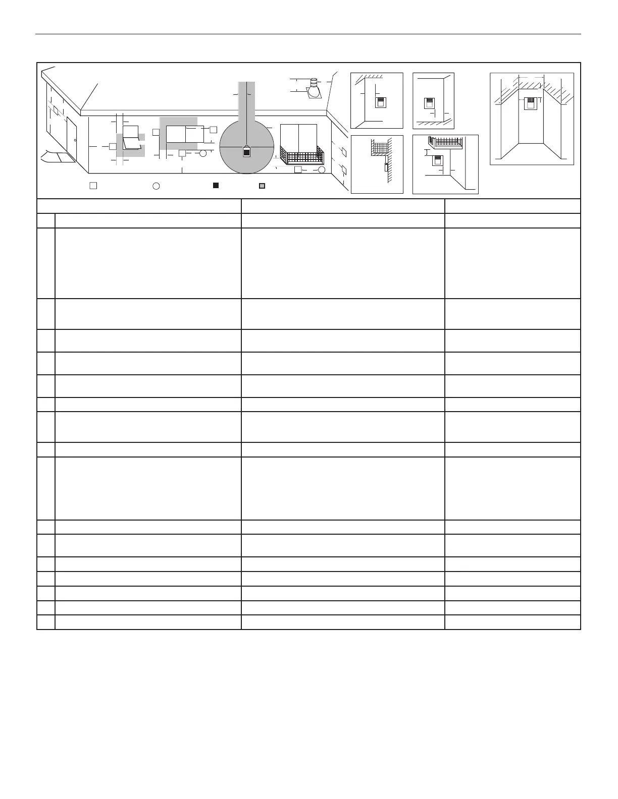
Table 7: Horizontal vent termination clearances for buildings with combustible and noncumbustible exteriors
Fixed
Closed
Openable
Fixed
Closed
V
V
V
V
V
V
X
X
V
X
G
G
J
F
B
B
K
H
I
A
E
L
D
B
M
C
B
V
V
A
G
G
B
TERMINATION CAP
AIR SUPPLY INLET
GAS METER RESTRICTED AREA
Openable
See Table 6
V
V
V
V
Outside Corner Recessed Location
Wall
V
Balcony with Perpendicular Side Wall
G
F
M
M
N
P
O
Q
U.S. Installation ** Canadian Installation *
A
Clearance above grade, veranda, porch, desk, or balcony 12” (300 mm) ** 12” (300 mm) *
B
Clearance to window or door that may be opened 6” (150 mm)
for fireplaces < 10,000 Btu/h (3 kW),
9” (230 mm)
for fireplaces > 10,000 Btu/h (3 kW), and < 50,000 Btu/h
(15 kW),
12” (300 mm)
for fireplaces > 50,000 Btu/h (15 kW) **
6” (150 mm)
for fireplaces < 10,000 Btu/h (3 kW),
12” (300 mm)
for fireplaces > 10,000 Btu/h (3 kW)
C
Clearance to permanently closed window 9” (229 mm)
recommended to prevent window condensation
12” (305 mm)
recommended to prevent
window condensation
D
Vertical clearance to ventilated soffit located above the
termination within a horizontal distance of 18” (458 mm)
18” (458 mm) 18” (458 mm)
E
Clearance to unventilated soffit 12” (305 mm) 12” (305 mm)
F
Clearance to outside corner 5” (127 mm)
minimum
5” (127 mm)
minimum
G
Clearance to inside corner 6” (152 mm) minimum 6” (152 mm) minimum
H
Clearance to each inside of center line extended above
meter / regulator assembly
36” (910 mm)
within a height of 15 ft above the meter / regulator assembly **
36” (910 mm)
within a height of 15 ft above the meter /
regulator assembly *
I
Clearance to service regulator vent outlet 36” (910 mm)** 36” (910 mm)*
J
Clearance to nonmechanical air supply inlet to building or
the combustion air inlet to any other fireplace
6” (150 mm)
for fireplaces < 10,000 Btu/h (3 kW),
9” (230 mm)
for fireplaces > 10,000 Btu/h (3 kW) and < 50,000 Btu/h (15 kW),
12” (300 mm)
for fireplaces > 50,000 Btu/h (15 kW)**
6” (150 mm)
for fireplaces < 10,000 Btu/h (3 kW),
12” (300 mm)
for fireplaces > 10,000 Btu/h (3 kW)
K
Clearance to a mechanical air supply inlet 36” (910 mm) above if within 10 ft (3 m) horizontally ** 72” (1830 mm) *
L
Clearance above paved sidewalk or paved diveway located
on public property
84” (2130 mm) ‡ 84” (2130 mm) ‡
M
Clearance under veranda, porch, deck or balcony 12” (300 mm) *‡ 12” (300 mm) *‡
N
Depth of alcove (maximum) 72” (1830 mm) ** 72” (1830 mm) *
O
Clearance to termination (alcove) 6” (15.2 mm) ** 6” (15.2 mm)*
P
Width of alcove (minimum) 36” (910 mm) ** 36” (910 mm) *
Q
Clearance to combustible above (alcove) 18” (457 mm) ** 18” (457 mm) *
*
**
‡
*‡
In accordance with the current CSA-B149.1 National Gas And Propane Installation Code
In accordance with the curent ANSI Z223.1/NFPA 54 National Fuel Gas Codes
A vent shall not terminate directly above a sidewalk or paved driveway which is located between two single family dwellings and serves both dwellings
Only permitted if veranda, porch, deck, or balcony is fully-open on a minimum two sides beneath the floor