Installation
900004-00, 01/2015
Innovative Hearth Products
Superior™ DRT2000 and DRC2000 Direct-Vent Gas Fireplaces
17
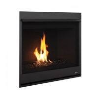
Table 11: Fireplace Framing Specifications
Model A * B C D E
Vent Framing—Top Vent
with One 90° Elbow
NOTE: Dimension “D” is the
required framing depth when
the finish material (drywall)
thickness is 1/2” (13mm).
Inches (millimeters)
Framing
construction to be
2 x 4, or larger.
B
C
D
A
1/2 A
5 1/8
(130)
7 (178)
12 1/8
(308)
10 1/2
(267)
E
DRC2033 /
DRT2033
33 3/4
857
34 1/4
870
36 7/8
930
14 1/2
368
19 5/8
499
DRC2035 /
DRT2035
35 3/8
899
34 1/4
870
38 3/4
984
18
447
23 3/8
594
DRC2040 /
DRT2040
40 3/8
1026
41 1/4
1048
43 3/4
1111
18
447
28 1/4
717
DRC2045 /
DRT2045
45 3/8
1153
41 1/4
1048
43 3/4
1111
18
447
28 1/4
717
C = Minimum height of top vent installations
E = Minimum height of rear vent installations
* Minimum opening size; additional 1/8” per side is recommended.
NOTE: Framing specifications do NOT apply for flexible venting.
When using flexible venting, refer to the kit requirements for
framing specifications.
NOTE: See Page 28 concerning use of compact terminations on
rear-vent 45” Models.
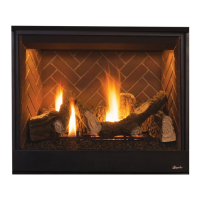
Table 12: Fireplace Framing Specifications—Corner Installation with Horizontal Termination
Model
A B C D E
F G
B
A
C
Inches
(millimeters)
D
E
Back wall of chase/enclosure (including finishing materials)
7
(178)
DRC/T2033
33 3/4
857
51 1/4
1302
36 1/4
921
25 5/8
651
12 1/8
308
5 1/2
140
14 1/2
368
DRC/T2035
35 3/8
899
59 1/2
1511
42 1/16
1068
3. 1/4
768
14 1/4
362
6 5/8
168
18
457
DRC/T2040
40 3/8
1026
63 13/16
1621
45 11/32
1152
32 3/16
818
15 7/8
403
8 1/2
216
18
457
DRC/T2045
45 3/8
1153
70 3/8
1788
49 3/4
1264
35 1/4
895
17 1/2
445
10 1/4
260
18
457
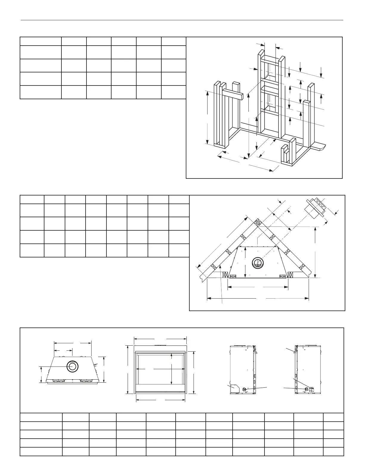
Table 13: Fireplace Specifications
NOTE: When finishing the area around the hood, 5/8” clearance above hood is required for hood installation.
Top View Front View
Left Side View Right Side View
E
F
G
H
J
K
L
M
Blower
access panel
Hood
Junction
box access
Gas line
access
N
O
Model E F G H (door) J K L M N O
DRC2033 / DRT2033 30 1/8 (765) 26 1/4 (667) 18 5/16 (465) 30 1/2 (775) 33 5/8 (854) 21 7/8 (556) 10 15/16 (278) 31 (787) 8 1/2 (216) 14 (356)
DRC2035 / DRT2035 32 1/8 (816) 28 3/4 (730) 22 1/4 (565) 32 3/8 (822) 35 1/4 (895) 25 (635) 12 1/2 (317) 32 7/8 (835) 10 1/16 (256) 17 (432)
DRC2040 / DRT2040 37 1/8 (943) 33 1/4 (845) 27 1/4 (692) 37 3/8 (949) 40 1/4 (1022) 30 (762) 15 (381) 37 7/8 (962) 10 1/16 (256) 17 (432)
DRC2045 / DRT2045 37 1/8 (943 33 1/4 (875) 27 1/4 (692) 42 3/8 (1076) 45 1/4 (1149) 35 (889) 17 1/2 (445) 42 7/8 (1089) 10 1/16 (256) 17 (432)
F*
G