Installation
900004-00, 01/2015
Innovative Hearth Products
Superior™ DRT2000 and DRC2000 Direct-Vent Gas Fireplaces
25
8. Change vent direction of horizontal/inclined run—Install the SV4.5E45 and SV4.5E90 elbows in the same
manner as the straight vent sections. See Vent elbows on Page 21 for more information.
9. Continue installation of horizontal/inclined sections—Continue with the installation of the straight vent
sections in horizontal/inclined run. Install support straps every 5 ft (1.52 m) along horizontal/inclined vent runs
using conventional plumber’s tape.
Rise per foot run ratios are acceptable all the way to level. For best results, maintain the horizontal/inclined run in
a straight (no dips), slightly elevated plane of approximately 1/4” per 1 ft (20 mm per 1 m).
Maintain the required clearances to combustibles (Page 23).
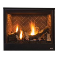
10. Frame the roof opening—Identify the location for the vent at the roof. Cut and/or frame opening (Table 16).
Table 16: Roof Framing Dimensions
Pitch C D
0/12 10 1/2” (267 mm) 10 1/2” (267 mm)
6/12 10 1/2” (267 mm) 12” (305 mm)
12/12 10 1/2” (267 mm) 17 3/4” (451 mm)
11. Install the roof flashing—Extend the vent sections through the roof structure. Install the roof flashing over the
vent section and position such that the vent column rises vertically (use carpenters level). Nail along perimeter
to secure flashing or adjust roofing to overlap the flashing edges at top and sides only and trim where necessary.
Seal the top and both sides of the flashing with waterproof caulking.
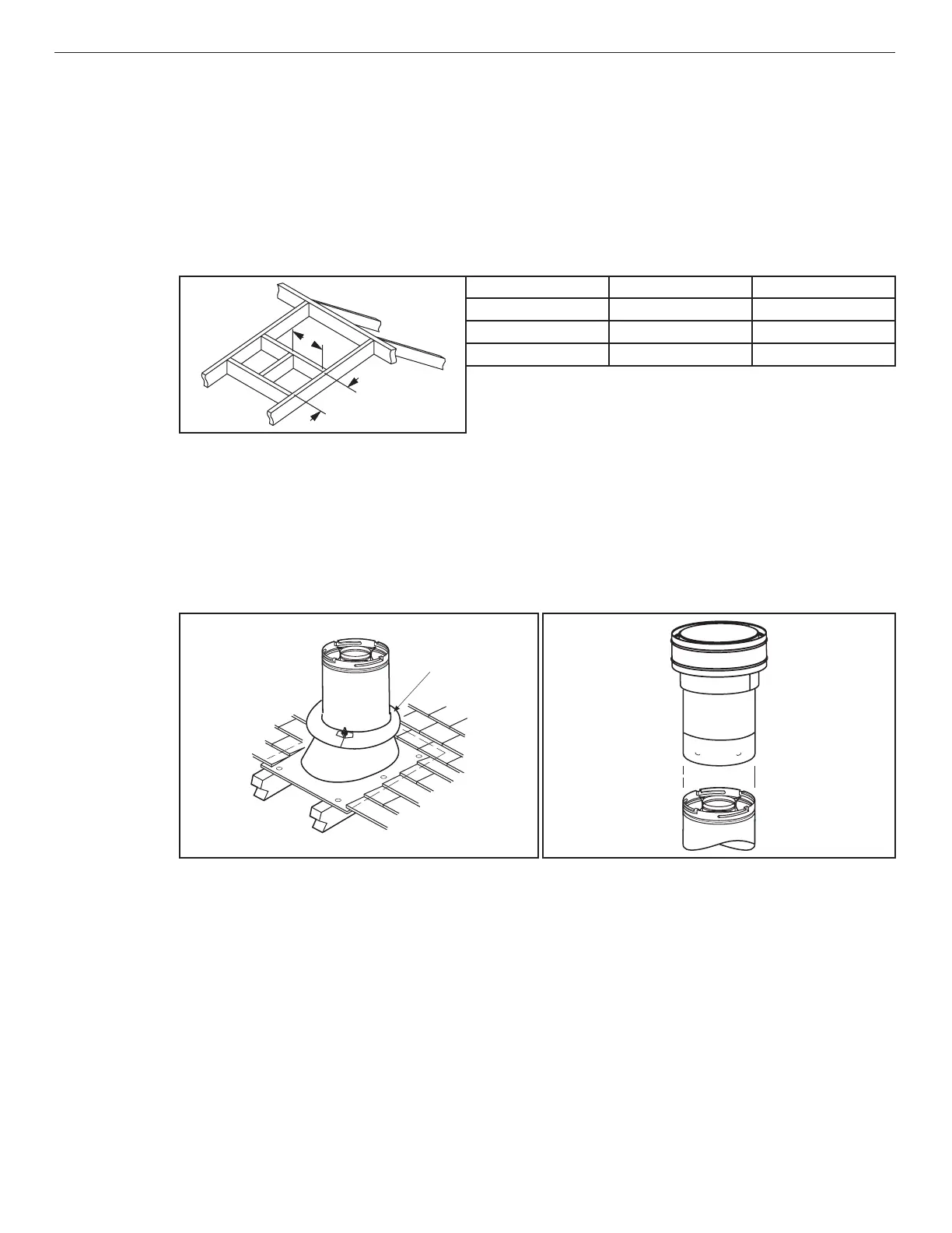
12. Install the storm collar—Install the storm collar, supplied with the flashing, over the vent/flashing joint
(Figure 23). Loosen the storm collar screw. Slide collar down until it meets the top of the flashing. Tighten the
adjusting screw. Apply non-combustible caulking or mastic around the circumference of the joint to provide a
water tight seal.
Figure 23: Installing the Storm Collar Figure 24: Installing the Vertical Termination
13. Install the vertical termination—The final step involves installation of the SV4.5CGV-1 vertical termination.
Extend the vent sections to the correct height (Figure 4). The SV4.5CGV-1 Vertical Termination (Figure 24)
installs in the exact same fashion as any other Secure Vent
®
section. Align the termination over the end of the
previously installed section, adjusting the radial alignment until the four (4) locking dimples of the termination
are aligned with the inlets of the four (4) incline channels of the last vent section. Push the termination down
until it fully engages, then twist the termination clockwise running the dimples down and along the incline
channels until they seat at the end of the channels.
If the vent system extends more than 5 ft (1.5 m) above the roof flashing, stabilizers may be necessary.
Additional screws may be used at section joints for added stability. Guide wires or roof support assemblies may
be attached to the joint for additional support on multiple joint configurations.