Installation
900004-00, 01/2015
Innovative Hearth Products
Superior™ DRT2000 and DRC2000 Direct-Vent Gas Fireplaces
30
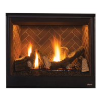
Figure 27: Installing the Horizontal Termination
Termination
10 1/2”
(267mm)
7”
(178)
5 1/8”
(130 mm)
12 1/8”
(308 mm)
Note: Centerline of Vent Piping is
NOT the Same as the Centerline of
the Framed Opening.
6 to 48” Vent Section,
Telescopic vent section,
Elbow or Appliance Collar
Min. Distance to Base
of Appliance.
Base of Appliance
3”
(76 mm)
1”
(25.4 mm)
Adapter
SV4.5RCH
To help minimize water
infiltration it is recommended that
the Firestop/Spacer (SV4.5HF)
be installed on the exterior
side of the wall.
See Table 11 for the minimum distance
to the base of the fireplace.
NOTE: To help minimize water infiltration install the firestop/spacer (SV4.5HF) on the exterior side of the wall.
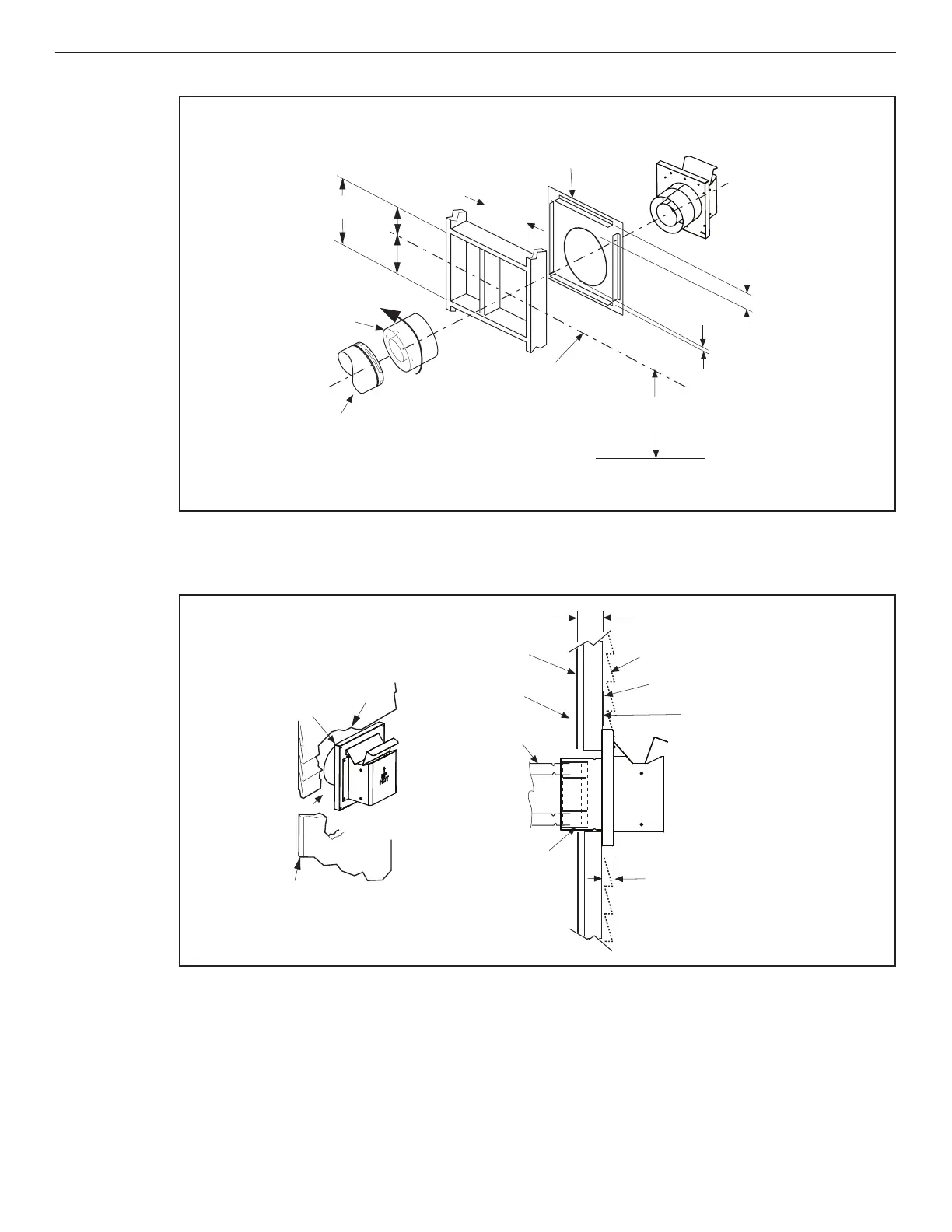
Figure 28: Venting Connection and Exterior Wall Recessing of the Horizontal Compact Termination
(SV4.5HTKCT)
Siding
Stucco
1-1/4” Maximum Recess of
the Square Termination into
Exterior Finishing Material
Exterior Surface of
Framing
6 in. to 9 1/4”
(152 to 235 mm)**
Exterior Surface of Siding
Interior Surface of
Finished Wall
Maximum wall thickness
9 1/4” (235 mm)**
Maximum Extent of
Vent Run Sections
Relative to Exterior
Surface of Framing
Last Vent Section. Use
Telescopic Vent
Section (SV4.5LA), If
Necessary
Adapter
SV4.5RCH
*Use silicone caulking to
seal the top and sides of
the termination, up to the
underlayment, stucco, or
masonry wall surface.
*Caulk
*Caulk
** For thicknesses greater
than 10” (254 mm) see
Table 21.