NOTE: DIAGRAMS & ILLUSTRATIONS ARE NOT TO SCALE.
Figure 43: Burner Bosses and Landings
Boss #4
Boss #3 Landing for Log C
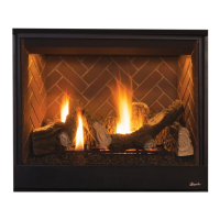
9-7. Place notch on underside of Right Rear Log B (Figure 45) over
Boss #2 (Figure 43).
Place opposite end of Right Rear Log B (Figure 45) on Landing for
Log B (see Figure 43).
29
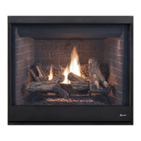
Figure 42: Top View of Logs
9-5. Install logs (reference Figure 42 and Table 9).
Note: Logs are FRAGILE! Handle with care to prevent breakage.
Boss #1 Boss #2
[CONTROL SIDE]
Landing for Log B
FIREBOX ACCESSORIES/PARTS
Cat. No. Model Description
H8312 PGE Bag of Glowing Embers
80L42 FDVS Bag of Volcanic Stone
Table 9
LOG SET
Item* Description Item* Description
A
Log, Center
D
Log, Top Right
B
Log, Right Rear
E
Log, Top Left
C
Log, Left Front
F
Log, Top Front
*Item letters correspond to photos.
Right Rear Log
Center Rear Log
Left Rear Log
Left Front Log
Right Front Log
Center Log
9-6. Place rectangular notches on underside of Center Log A (Figure
44) over Boss #1 and Boss #4 (Figure 43).
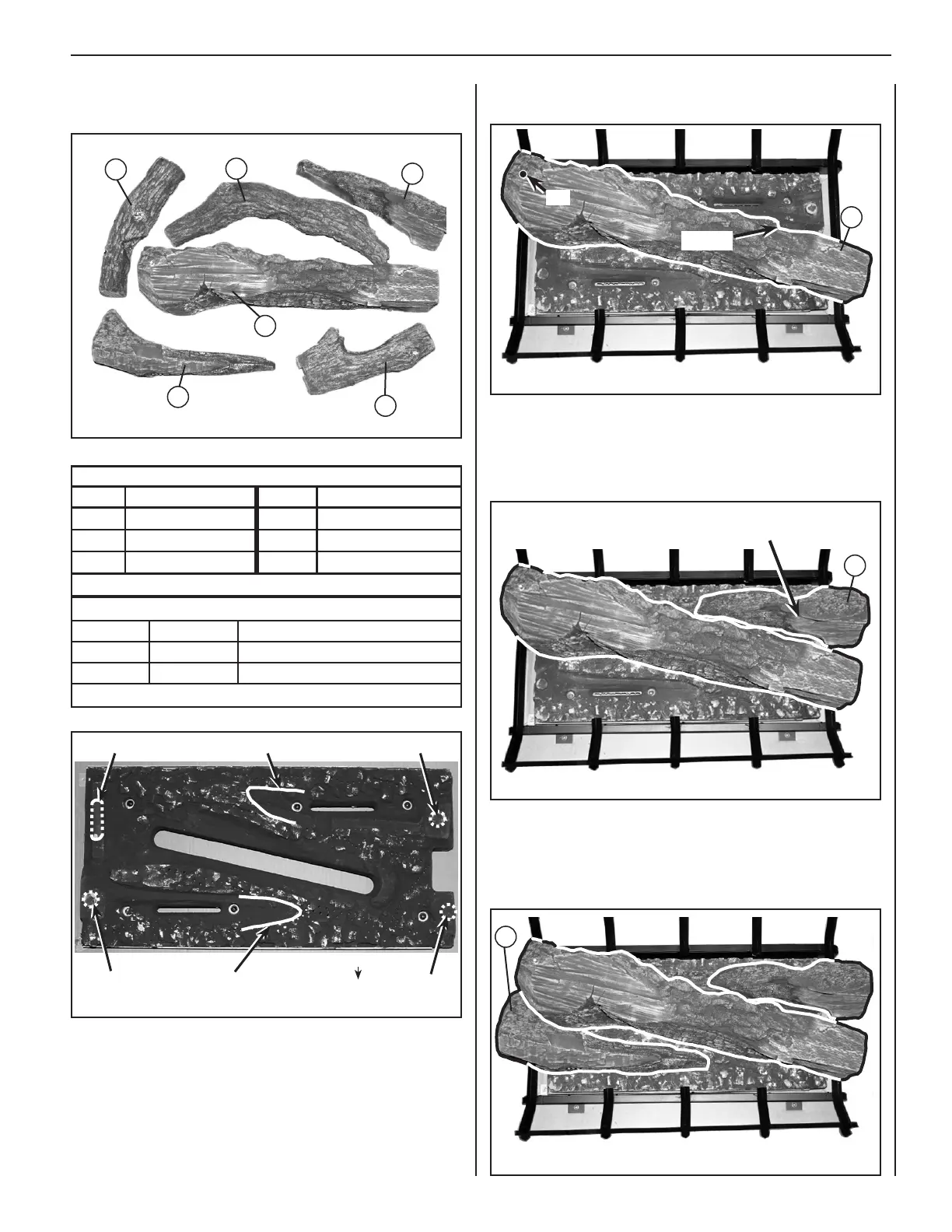
9-8. See Figures 43 and 46. Place notch on underside of Left Front
Log C over Boss #3.
Place opposite end of Left Front Log C on Landing for Log C (see
Figure 43).
Figure 46
F
A
E
D
B
Figure 45
Landing for Log D
(see Step 9-9 and Figure 47 on next page)
B
Figure 44
Pin
Landing
A
INNOVATIVE HEARTH PRODUCTS • SEE-THROUGH DIRECT-VENT GAS FIREPLACES (DRT63STTEN/P) • INSTALLATION INSTRUCTIONS
C
C